Head Up Display Dynamic And Static Distortion Measurement And Specification Using Programmable And Automated XYZLDA Positioning System And Still/Video Camera

a head-up display and positioning system technology, applied in the direction of polarising elements, instruments, structural/machine measurement, etc., can solve the problems of static and dynamic distortion of virtual images, dynamic distortion occurring when the virtual image changes, and the definition and specification of dynamic distortions have not been fully characterized by oems or suppliers, so as to achieve accurate definition of distortions

Inactive Publication Date: 2019-02-28
PANASONIC AUTOMOTIVE SYST OF AMERICA
View PDF3 Cites 7 Cited by
  • Summary
  • Abstract
  • Description
  • Claims
  • Application Information

AI Technical Summary

Benefits of technology

[0009]Motion in the X-axis accurately locates image recording equipment in front/rear eye box location. Motion in the Y-axis and the Z-axis results in image recording equipment traversing horizontally, vertically or diagonally within the eye box at any specified vertical or horizontal location. This traverse can be continuous where speed of traverse can be specified or incremental where incremental steps and duration are specified. The virtual image

Problems solved by technology

A Head Up Display is an optical system and as such produces static and dynamic distortions of the virtual image.
Dynamic distortion occurs when the virtual image changes as the viewer's eye moves continuously within the eye box.
This dynamic distortion is a continuous distortion o

Method used


Image

  • Head Up Display Dynamic And Static Distortion Measurement And Specification Using Programmable And Automated XYZLDA Positioning System And Still/Video Camera
  • Head Up Display Dynamic And Static Distortion Measurement And Specification Using Programmable And Automated XYZLDA Positioning System And Still/Video Camera

Examples


Embodiment Construction

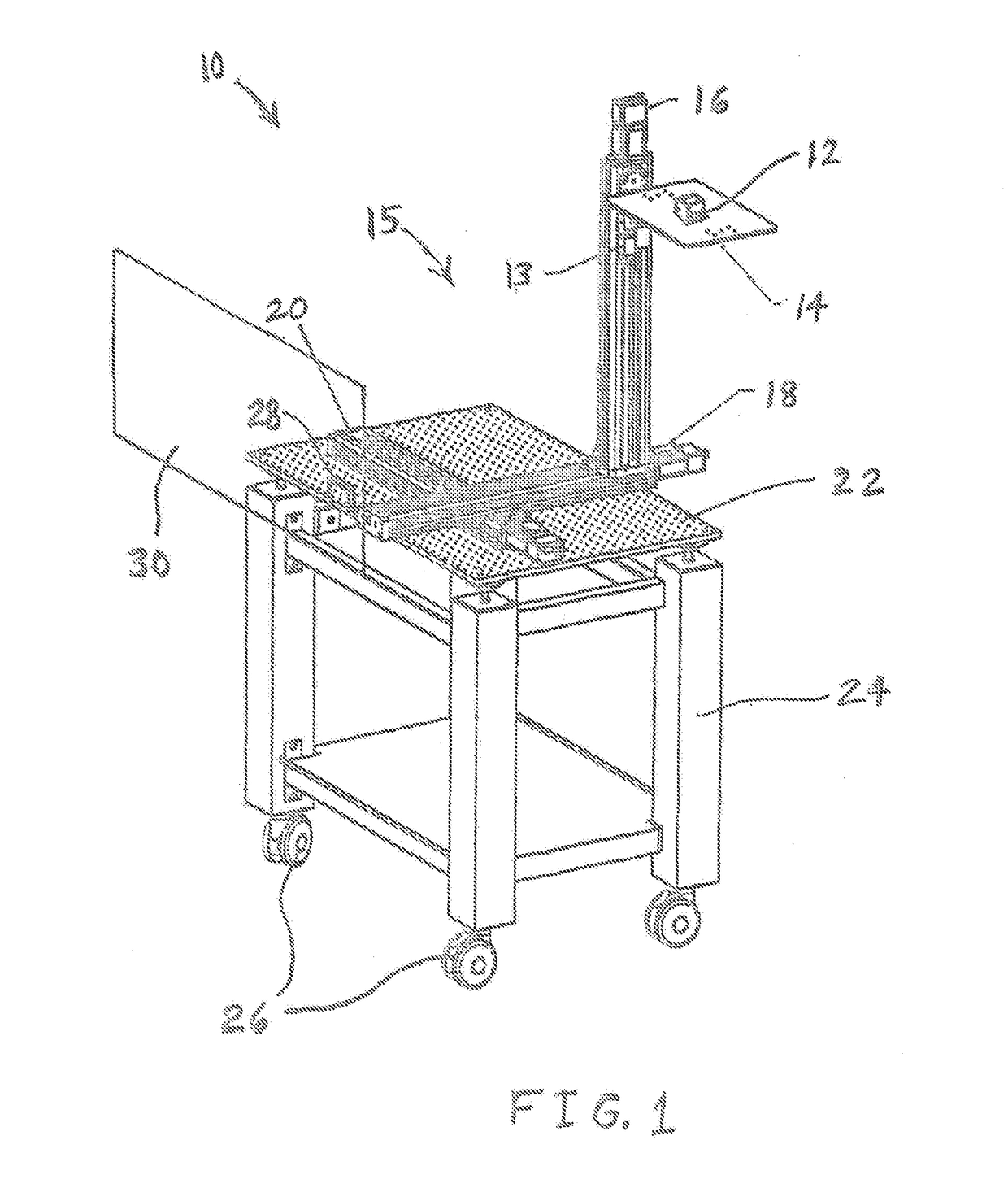
[0016]FIG. 1 illustrates one embodiment of a head up display testing apparatus 10 of the present invention, including an optical instrument in the form of a camera, photoradiometer or other optical instrument 12 mounted on a tilt platform or instrument shelf 14. Tilt platform 14 is mounted on a rotary drive module 13 which in turn is mounted on a three-dimensional positioning assembly 15 including linear drive modules 20, 16, 18 for the y-axis, z-axis, and x-axis, respectively. Y-axis linear drive module 20 is mounted to a horizontally-oriented board 22 of an optics cart 24 on wheels 26. Camera, photoradiometer or other optical instrument 12 may capture virtual images produced by a HUD projector 28 reflecting a light field off of a windshield 30. The travel distances of the X, Y, Z stages may be different from each other to accommodate the requirements of HUD measurements for field of view, eyebox size, and optical table height.

[0017]) Each one of the y-axis linear drive module 20, ...


PUM


Abstract

A head up display testing arrangement includes an optical instrument detecting an optical quality of a light field produced by a head up display projector. A rotatable support device is attached to and supports the optical instrument. A three-dimensional positioning assembly is attached to and supports the tiltable support device. The three-dimensional positioning assembly includes an x-axis linear drive module, a y-axis linear drive module, and a z-axis linear drive module. Each one of the x-axis linear drive module, the y-axis linear drive module, and the z-axis linear drive module translates the tiltable support device in a direction orthogonal to directions in which other two of the x-axis linear drive module, the y-axis linear drive module, and the z-axis linear drive module translate the rotatable support device. A rollable cart is attached to and supports the three-dimensional positioning assembly.

Description

CROSS-REFERENCE TO RELATED APPLICATIONS[0001]This application claims the benefit of U.S. Provisional Application No. 62 / 552,808 filed on Aug. 31, 2017, which the disclosure of which is hereby incorporated by reference in its entirety for all purposes.FIELD OF THE INVENTION[0002]The disclosure relates to a head up display (HUD) in a motor vehicle.BACKGROUND OF THE INVENTION[0003]A head up display emits light that reflects from the front windshield to be seen by the driver. The light appears to come from a virtual image in front of the driver and in front of the windshield. This type of head up display is currently commercially available.[0004]Conventional head up displays create the virtual image by first using a display to create an image. Next, the light from the image is reflected from one or more mirrors. Next, the light from the mirrors is reflected from the windshield. The mirrors are designed and positioned relative to the display so that the light seen by the driver, which is...

Claims


Application Information

Patent Timeline
IPC IPC(8): G02B27/01G01M11/02G02B5/30
CPCG02B27/0101G01M11/02G02B5/30G02B2027/0141G01M11/0207G01M11/0257G02B27/62G02B27/0075
Inventor TANG-KONG, GERALDBURNS, TOM
Owner PANASONIC AUTOMOTIVE SYST OF AMERICA
Why Eureka
Try Eureka