
Electroluminescent display device

a technology display device, which is applied in the direction of instruments, optical elements, polarising elements, etc., can solve the problems of color mixing, affecting reducing the out-coupling efficiency so as to improve the reliability improve efficiency and power consumption of electroluminescent display device, and vivid images

Active Publication Date: 2019-02-28
LG DISPLAY CO LTD
View PDF6 Cites 7 Cited by
  • Summary
  • Abstract
  • Description
  • Claims
  • Application Information

AI Technical Summary

Benefits of technology

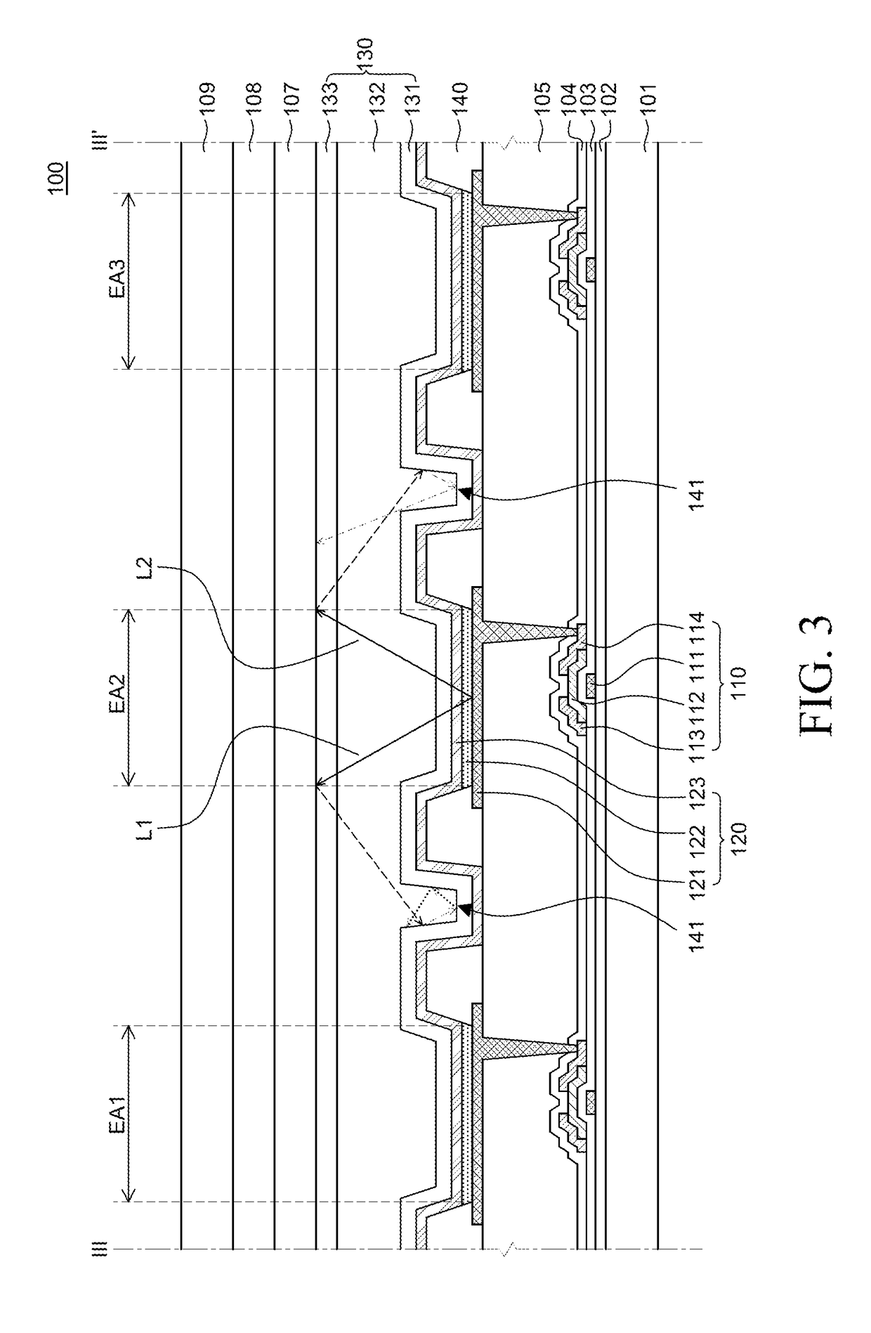
This patent is about a new electroluminescent display device that improves out-coupling efficiency and prevents color mixing. The device includes a substrate, anodes, a bank, emission layers, and cathodes. By designing the bank with openings and holes, the device can suppress color mixing that occurs when light is reflected from one area to another. This improves the efficiency and power consumption of the display device, and can enhance reliability and achieve vivid images. Overall, the patent proposes a solution for improving the performance of electroluminescent display devices.

Problems solved by technology

However, some of the light emitted from the emission layer fail to exit out of the electroluminescent display device and are confined therein due to total reflection.
This can decrease the out-coupling efficiency of the electroluminescent display device.
The inventors of the application have recognized a problem that some of the light emitted from an emission layer of an electroluminescent display device fail to exit out of the electroluminescent display device due to total reflection and are confined therein.
In addition, the inventors of the application have recognized a problem that when light emitted from an electroluminescent element disposed in an emission area is totally reflected inside the electroluminescent display device and travels to an adjacent emission area, color mixing may occur.

Method used


Image

  • Electroluminescent display device
  • Electroluminescent display device
  • Electroluminescent display device

Examples


Embodiment Construction

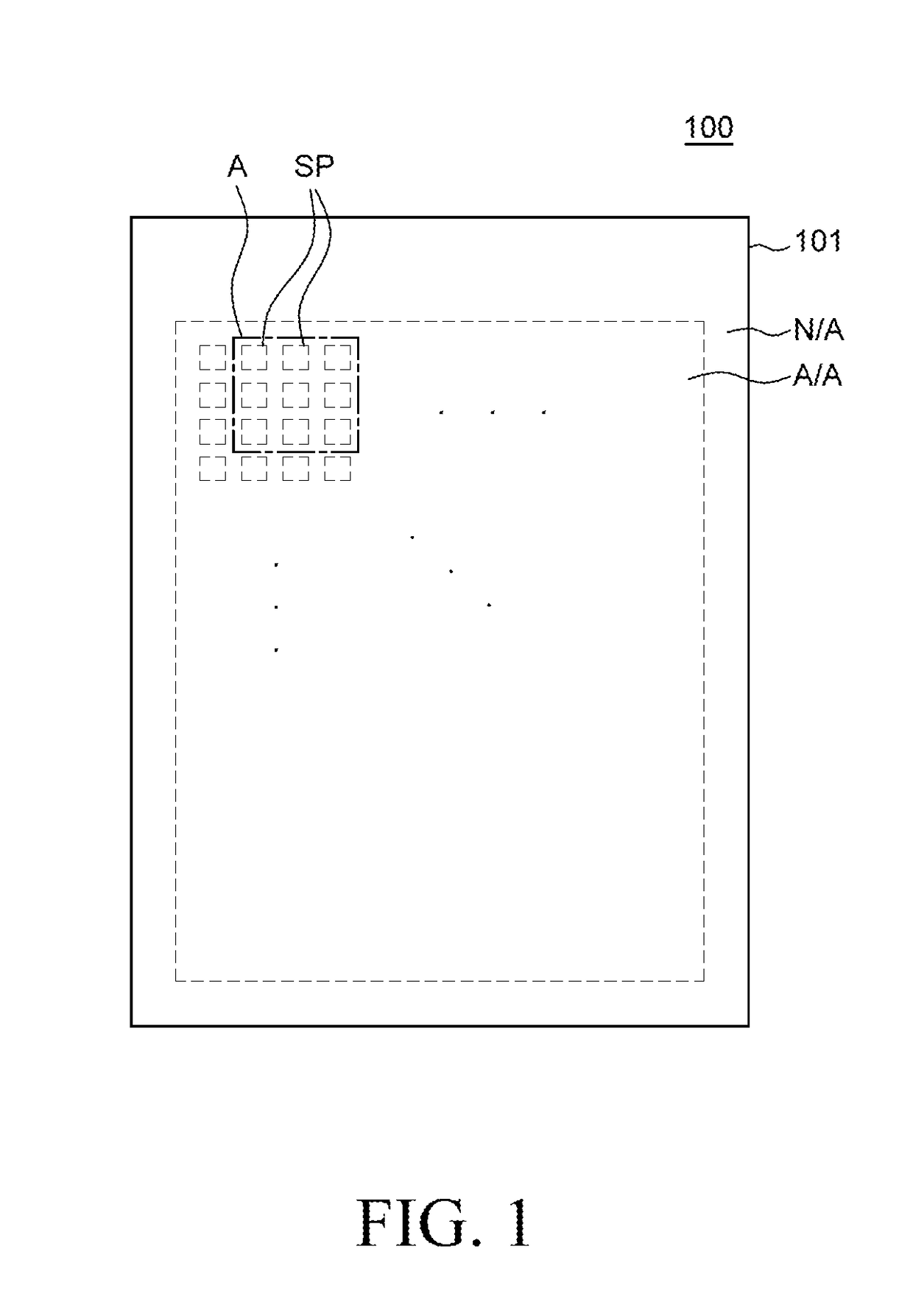
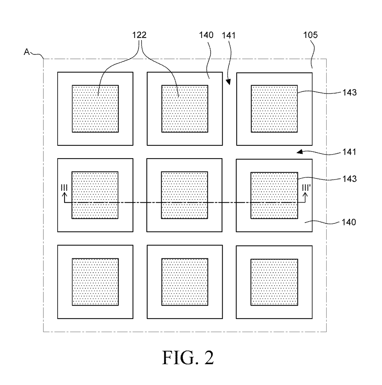
[0030]Advantages and features of the present disclosure and methods to achieve them will become apparent from the descriptions of exemplary aspects hereinbelow with reference to the accompanying drawings. However, the present disclosure is not limited to exemplary aspects disclosed herein but may be implemented in various different ways. The exemplary aspects are provided for making the present disclosure thorough and for fully conveying the scope of the present disclosure to those skilled in the art. It is to be noted that the scope of the present disclosure is defined only by the claims.

[0031]The figures, dimensions, ratios, angles, the numbers of elements given in the drawings are merely illustrative and are not limiting. Like reference numerals denote like elements throughout the descriptions. Further, in describing the present disclosure, descriptions on well-known technologies may be omitted in order not to unnecessarily obscure the gist of the present disclosure. It is to be ...


PUM


Abstract

Disclosed herein is an electroluminescent display device. The electroluminescent display device includes: a substrate; a plurality of anodes disposed on the substrate; a bank disposed over the substrate and the plurality of anodes, the bank comprising a plurality of openings each exposing a part of the respective anodes, and one or more holes formed between the openings; a plurality of emission layers on each of the anodes; and a plurality of cathodes on each of the emission layers. It is possible to suppress the color mixing occurring when light emitted from a electroluminescent element is reflected to another emission area for representing a different color rather than its emission area.

Description

CROSS REFERENCE TO RELATED APPLICATION[0001]This application claims the priority of Korean Patent Application No. 10-2017-0109987 filed on Aug. 30, 2017, in the Korean Intellectual Property Office, the disclosure of which is incorporated herein by reference in its entirety.BACKGROUNDField of the Disclosure[0002]The present disclosure relates to an electroluminescent display device, and more particularly, to an electroluminescent display device capable of increasing out-coupling efficiency of light emitted from an electroluminescent element and suppressing light emitted from an electroluminescent element from being mixed with light emitted from another electroluminescent element.Description of the Background[0003]An electroluminescent display device is capable of producing light in its own and thus does not require any additional light source, unlike a liquid-crystal display (LCD) device. Therefore, an electroluminescent display device can be made lighter and thinner than an LCD devi...

Claims


Application Information

Patent Timeline
Patent Type & Authority Applications(United States)
IPC IPC(8): H01L51/52H01L27/32G06F3/044
CPCH01L51/5271H01L27/323H01L27/3246H01L51/5253H01L51/5268H01L51/5281G06F3/044G02B5/30G02B5/0242G06F3/041G02B5/045H10K59/122H10K59/878H10K59/877H10K59/8791H10K59/8731H10K77/10H10K50/81H10K50/82H10K50/841H10K59/40H10K50/856H10K50/86H10K50/854H10K50/844
Inventor CHOI, WONJINCHAE, GEESUNGKIM, JIGON
Owner LG DISPLAY CO LTD
Learn More