Plasma deposition method

Inactive Publication Date: 2019-03-28
HZO INC
View PDF0 Cites 0 Cited by
  • Summary
  • Abstract
  • Description
  • Claims
  • Application Information

AI Technical Summary

Benefits of technology

The patent describes a way to clean plasma chambers by depositing a layer of material on the inside walls before coating them. This layer helps to remove any materials that may accumulate during the coating process. This method does not increase the time it takes to pump down the chamber and can make the coating process more efficient.

Problems solved by technology

The presence of the cover layer does not increase the pumping down time in the plasma deposition process, and thus the efficiency of the process is not reduced by the presence of the cover layer.

Method used


Image

  • Plasma deposition method
  • Plasma deposition method
  • Plasma deposition method

Examples


example 1

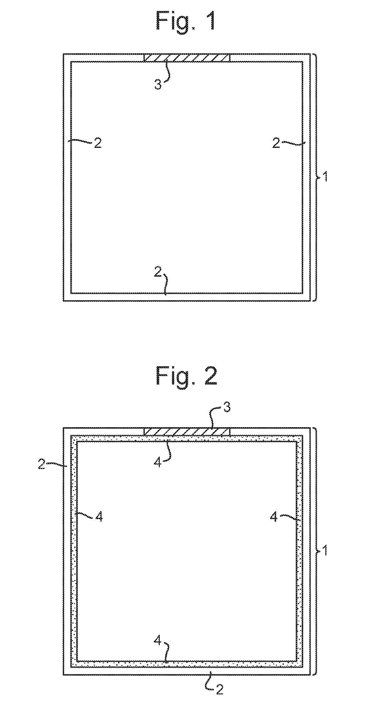
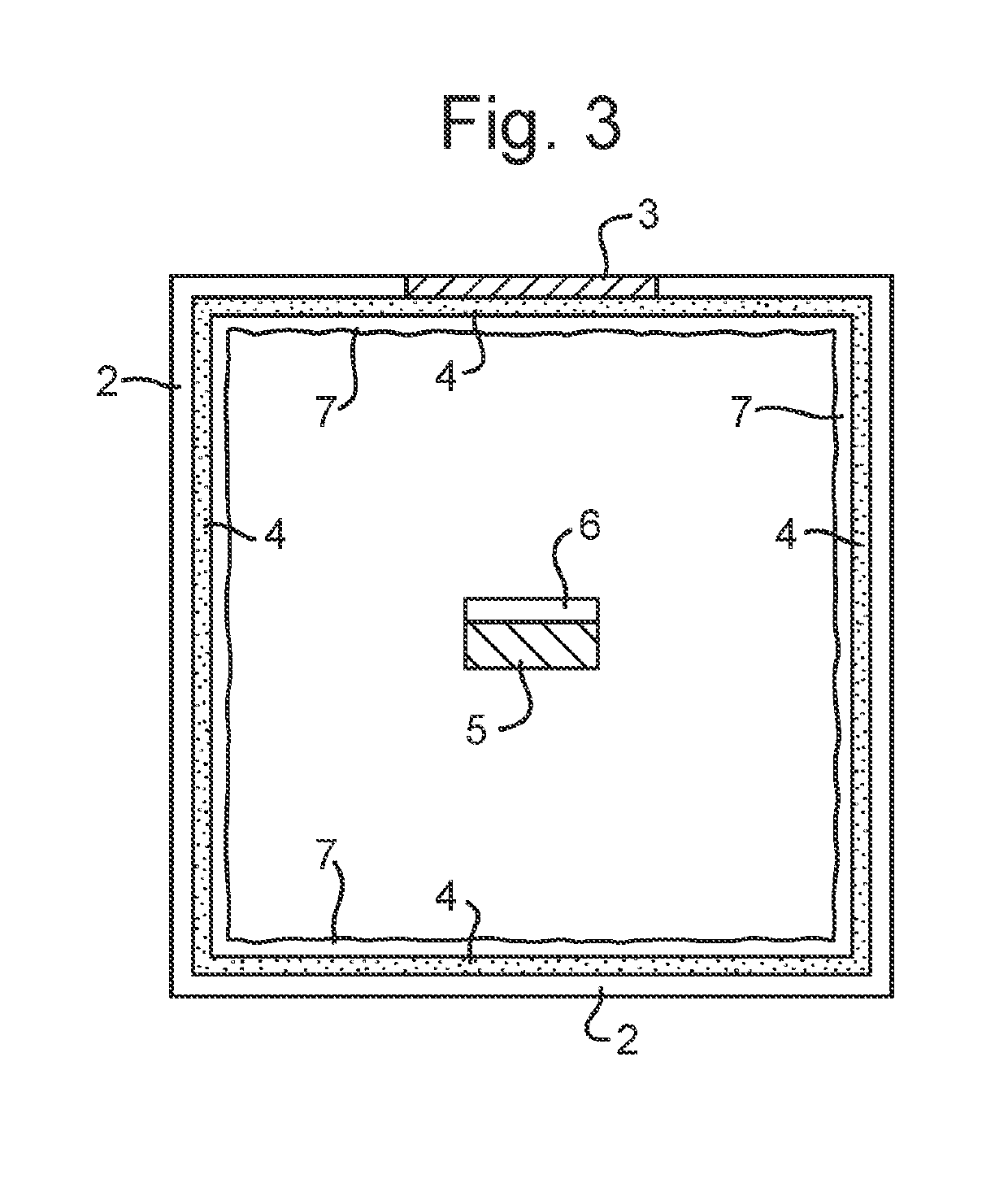
[0081]A cover layer is first deposited on the internal surfaces of an empty plasma chamber (i.e. a plasma chamber that does not contain an electrical assembly) by plasma deposition of 1,4-dimethyl benzene. The resulting cover layer of formula CmHn is 200 nm thick. The capped plasma chamber is then used to deposit conformal coatings on electrical assemblies using the techniques described in WO 2013 / 132250.

[0082]During deposition of the conformal coatings onto the electrical assemblies, materials are deposited also onto the cover layer. Once preparation of the electrical assemblies with conformal coatings is complete, the internal surfaces of the plasma chamber are cleaned using vacuum suction. The vacuum suction removes both the cover layer and the materials deposited on it during deposition of the conformal coatings, leaving a clean plasma chamber with uncoated internal surfaces.


PUM

PropertyMeasurementUnit
Thicknessaaaaaaaaaa
Thicknessaaaaaaaaaa
Pressureaaaaaaaaaa

Abstract

A plasma deposition method in which a cover layer is deposited onto the internal walls of an empty plasma chamber by plasma deposition of a precursor mixture comprising (i) one or more hydrocarbon compounds of formula (A), or (ii) one or more C1-C3 alkane, C2-C3 alkene or C2-C3 alkyne compounds: (Formula (A)) wherein: Z1 represents C1-C3 alkyl or C2-C3 alkenyl; Z2 represents hydrogen, C1-C3 alkyl or C2-C3 alkenyl; Z3 represents hydrogen, C1-C3 alkyl or C2-C3 alkenyl; Z4 represents hydrogen, C1-C3 alkyl or C2-C3 alkenyl; Z5 represents hydrogen, C1-C3 alkyl or C2-C3 alkenyl; and Z6 represents hydrogen, C1-C3 alkyl or C2-C3 alkenyl.

Description

FIELD OF THE INVENTION[0001]The present invention relates to a method for preparing a cover layer for the internal walls of plasma chambers, to subsequent deposition of conformal coatings onto electrical assemblies using plasma chambers with this cover layer, and to subsequent removal of the cover layer and materials deposited thereon during formation of the conformal coating.BACKGROUND TO THE INVENTION[0002]Conformal coatings have been used for many years in the electronics industry to protect electrical assemblies from environmental exposure during operation. A conformal coating is a thin and flexible layer of protective lacquer that conforms to the contours of an electrical assembly, such as a printed circuit board, and its components. Plasma deposited coatings have emerged as promising alternatives to conventional conformal coatings, and have been described in, for example, WO 2013 / 132250.[0003]The plasma deposition process involves placing the electrical assembly onto which the...

Claims


Application Information

Patent Timeline
IPC IPC(8): C23C16/503C23C16/02C23C16/56C23C16/44C23C16/511B05D1/00B05D3/00
CPCC23C16/503C23C16/0272C23C16/56C23C16/4407C23C16/4404C23C16/511B05D1/62B05D3/002B05D2259/00C23C16/30C23C16/505H01J37/32477
Inventor SINGH, SHAILENDRA VIKRAMLIONE, RICHARD ANTHONY
Owner HZO INC
Why Eureka
Try Eureka