Solar cell module

Inactive Publication Date: 2015-07-02
PANASONIC INTELLECTUAL PROPERTY MANAGEMENT CO LTD
View PDF4 Cites 0 Cited by
  • Summary
  • Abstract
  • Description
  • Claims
  • Application Information

AI Technical Summary

Benefits of technology

The present invention describes a solar cell device that has a lamination structure of two sealing materials, with a porous body in between. This structure prevents the opaque lower sealing material from protruding, which could reduce power generation efficiency. Additionally, the lower sealing material does not flow easily during reliability tests, which increases the likelihood of failure. As a result, the solar cell module described herein has improved power generation efficiency and is less likely to fail.

Problems solved by technology

Furthermore, the softened lower sealing material does not easily flow in a reliability test in which heat is applied from the outside such as a heat cycle test.
As a result, it is possible to realize the solar cell module in which a failure due to generation of the protruding portion of the opaque lower sealing material does not easily occur and power generation efficiency is not reduced.

Method used


Image

  • Solar cell module
  • Solar cell module
  • Solar cell module

Examples


embodiment 1

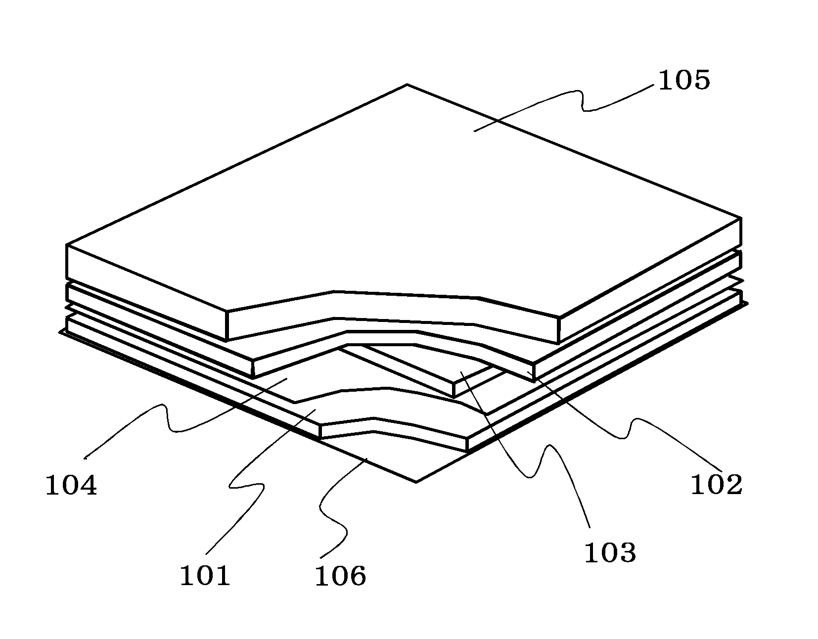
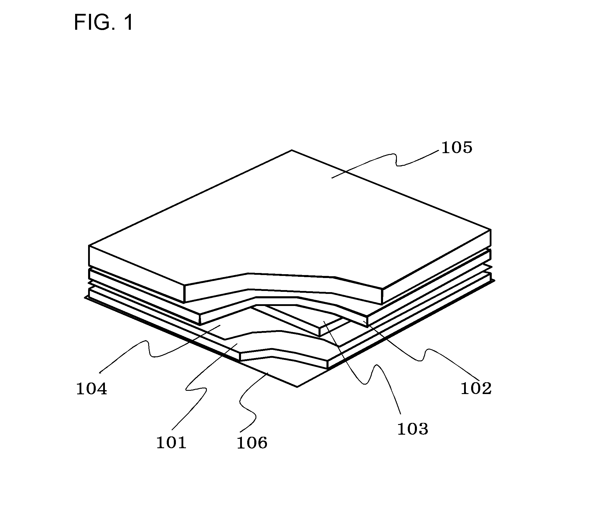
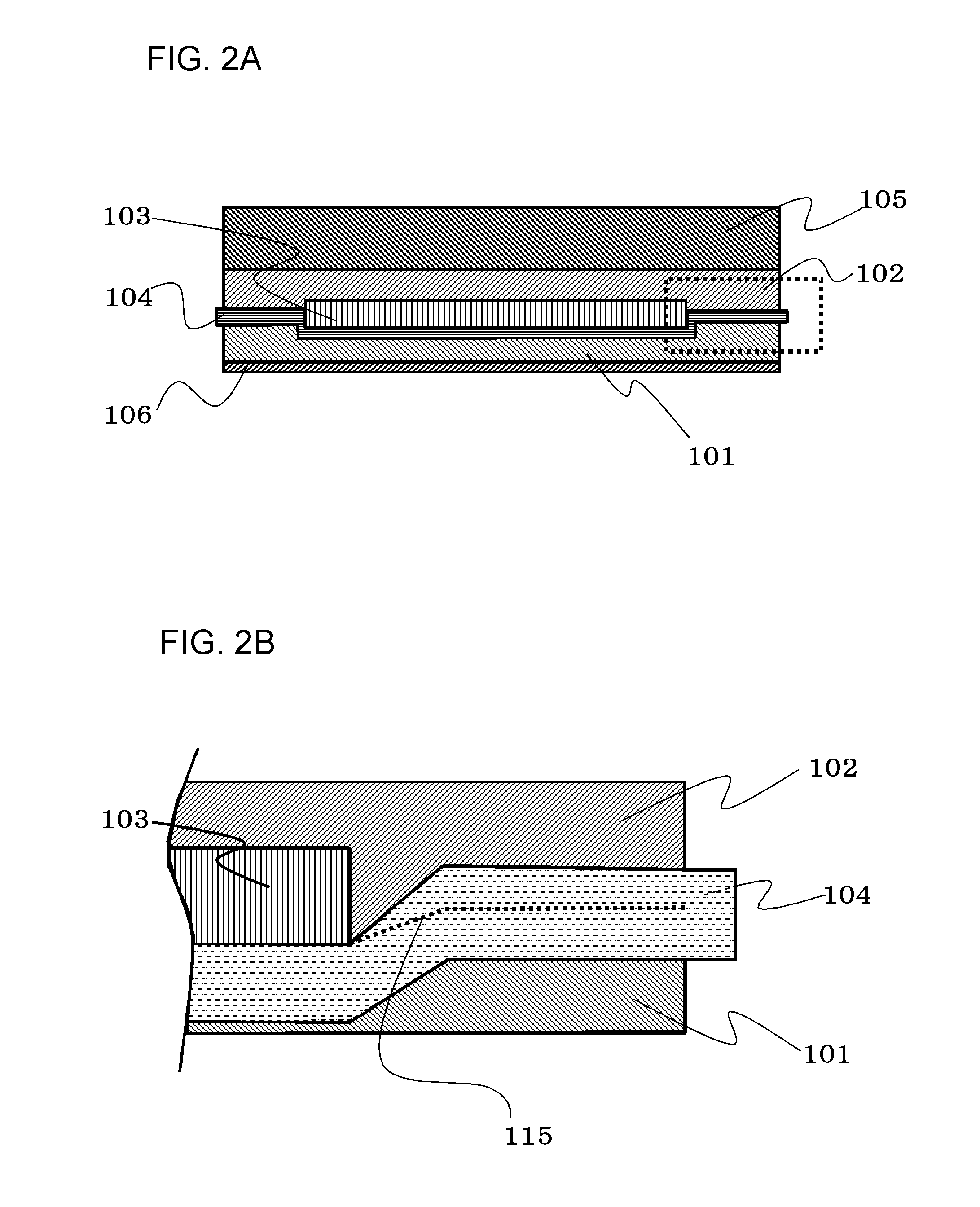
[0029]FIG. 1 is a perspective view showing a state where part of a solar cell module according to Embodiment 1 is peeled, FIG. 2A is a cross-sectional view thereof and FIG. 2B is a cross-sectional view obtained by enlarging a portion surrounded by dotted lines of FIG. 2A.

[0030]The solar cell module according to Embodiment 1 includes a solar cell device 103, an upper sealing portion 102 positioned over the solar cell device 103, a porous body 104 positioned below the solar cell device 103, a lower sealing portion 101 positioned below the porous body 104, an uppermost protective member 105 positioned over the upper sealing portion 102 and a back sheet 106 positioned below the lower sealing portion 101.

[0031]The solar cell device 103 is sandwiched between the upper sealing portion 102 and the lower sealing portion 101. A dotted line of FIG. 2B denotes an interface 115 between the upper sealing portion 102 and the lower sealing portion 101.

[0032]Vacuum lamination is performed in a state...

embodiment 2

[0046]In Embodiment 2, a portion in which the solar cell device 103 is inserted is provided as an opening in the porous body 104. The opening will be explained with reference to FIG. 3A, FIG. 3B, FIG. 4A and FIG. 4B. Components not to be explained are the same as those of Embodiment 1.

[0047]FIG. 3A is a perspective view obtained by breaking a corner portion of the solar cell module. FIG. 3B is an exploded view for explaining the relation between the solar cell device 103 and the porous body 104. FIG. 4A is a cross-sectional view of the solar cell module and FIG. 4B is an enlarged cross-sectional view of a portion surrounded by dotted lines of FIG. 4A. A dotted line in FIG. 4B is an interface 115 between the sealing material of the upper sealing portion 102 and the sealing material of the lower sealing portion 101. A sealing resin enters the porous body 104.

[0048]An opening 114 is provided in the porous body 104 as shown in FIG. 3B, and the size of the opening 114 is larger than the ...

example 1

[0066]As the sealing material of the upper sealing portion 102, the ethylene-vinyl acetate copolymer (EVA) sheet with a total light transmittance of 92% (measured by Haze Meter-HR-100 manufactured by MURAKAMI COLOR RESEARCH LABORATORY) was used. As the sealing material of the lower sealing portion 101, a sealing material obtained by allowing the ethylene-vinyl acetate copolymer to contain 5 wt % rutile-type titanium dioxide with a total light reflectance of 75% (measured by Haze Meter-HR-100 manufactured by MURAKAMI COLOR RESEARCH LABORATORY) was used.

[0067]Subsequently, a polyester spunbond as an organic nonwoven fabric was used for the porous body 104.

[0068]As a lamination method, the EVA sheet with the total light transmittance of 92% as the sealing material of the upper sealing portion 102 was put on a white-plate tempered glass as the uppermost protective member 5, and the solar cell device 103 was put thereon. Next, the polyester spunbond as the organic nonwoven fabric was ove...


PUM


Abstract

To provide a solar cell module formed by a lamination structure in which a lower sealing portion (101) having a total light reflectance of 50% or more is arranged on a back sheet (106) side with respect to a solar cell device (103) and an upper sealing portion (102) having a total light transmittance of 50% or more is arranged on a solar-light irradiation surface side with respect to a solar cell device (103), and a porous body (104) is interposed between the lower sealing portion (101) and the solar cell device (103). To further provide a solar cell module in which an opening is formed in the porous body and the solar cell device is positioned in the opening.

Description

TECHNICAL FIELD[0001]The present invention relates to a structure for providing a solar cell device in a solar cell module.BACKGROUND ART[0002]The solar cell module is rapidly attracting attention as a safe and clean energy source which can be used instead of nuclear power generation. A public undertaking of large scale solar construction has begun at last in recent years. The solar cell module is also becoming common in ordinary houses for private use.[0003]However, the solar cell module has not become common in many ordinary houses as it is difficult to generate a sufficient amount of power for replacing the conventional power generation and equipment is expensive. As reasons for that, conversion efficiency of solar cells is low at 20%, and productivity of the solar cell module is low.[0004]Concerning improvement in conversion efficiency of the solar cells, study and development have been made night and day in universities and companies, making an effort to improve conversion effi...

Claims


Application Information

Patent Timeline
IPC IPC(8): H01L31/048H01L31/049
CPCH01L31/049H01L31/0481H01L31/048Y02E10/50
Inventor TSUJIMURA, HIDEYUKIOHASHI, NAOMICHI
Owner PANASONIC INTELLECTUAL PROPERTY MANAGEMENT CO LTD
Why Eureka
Try Eureka