Low temperature pallet stacker

Active Publication Date: 2021-05-04
HILGENDORF DENNIS J
View PDF16 Cites 0 Cited by
  • Summary
  • Abstract
  • Description
  • Claims
  • Application Information

AI Technical Summary

Benefits of technology

The pallet stacker is a manually operated apparatus that allows a single operator to stack and transport a number of pallets with minimal lifting. It can be used in refrigerated warehouses safely. The apparatus has a pivot frame that can be transitioned from a loading position to an unload position where the pallets are presented in a stacked horizontal arrangement for removal by a lift or crane. A damping assembly is used to control the speed of the transition of the pivot frame from the load position to the unload position. The damping assembly has a very small metering orifice and a check valve arrangement that helps in controlling the movement of air. The apparatus is designed to be easily operated and safer in environments where food is stored and moved.

Problems solved by technology

However, although this conventional air cylinder was effective at room temperature, it did not function reliably at very low temperatures of as much as −20 degrees Fahrenheit such as found in refrigerated warehouses.

Method used


Image

  • Low temperature pallet stacker
  • Low temperature pallet stacker
  • Low temperature pallet stacker

Examples


Embodiment Construction

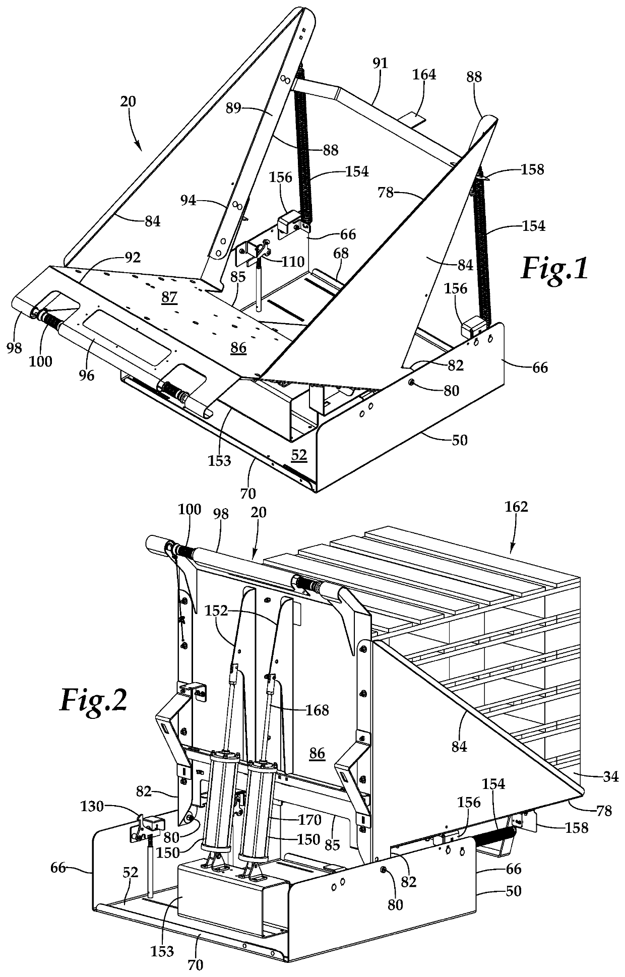
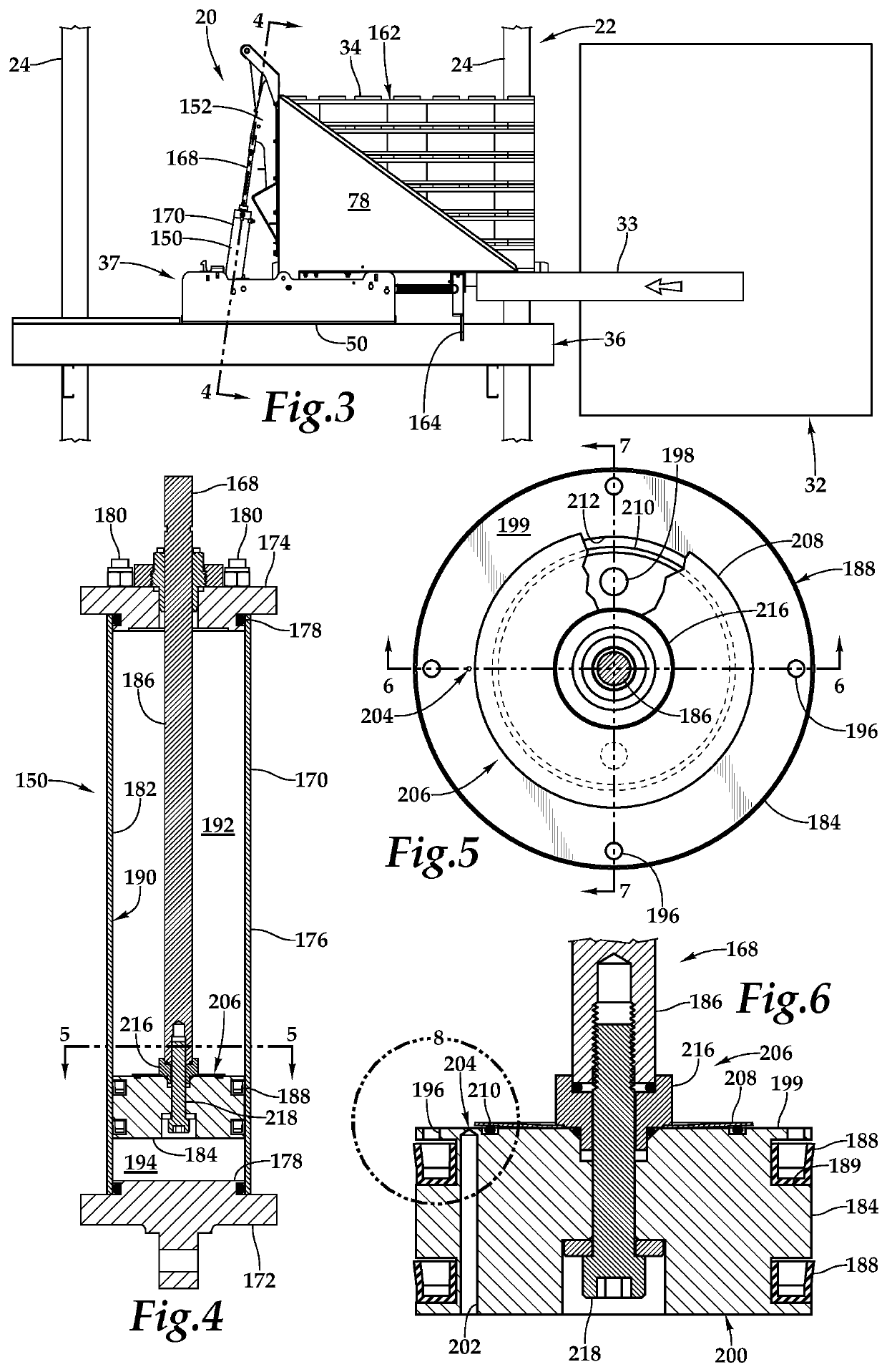
[0019]Referring more particularly to FIGS. 1-10, wherein like numbers refer to similar parts, a manual pallet stacker 20 of this invention is shown in FIG. 1. As shown in FIG. 3, the stacker 20 is mounted within a conventional rack 22 such as is commonly used in a refrigerated warehouse. The rack 22 has vertical members 24 which extend upwardly above a floor, not shown. The rack 22 is positioned alongside an unloading aisle 36 through which an apparatus for removing loads of pallets operates, for example an automated crane 32. The rack 22 will typically have multiple vertical levels spaced above a main floor. When the product on a pallet 34 has been depleted, the operator extracts the empty pallet from a rack bay containing product, and brings it along a loading aisle 37 to a return bay for assembly into a vertical stack of pallets and removal from the rack. Each return bay is outfitted with a stacker 20.

[0020]As shown in FIG. 1, the stacker 20 has a base 50 which is fixed to the ra...


PUM


Abstract

A pallet stacker has a pivot frame which is pivotable to receive pallets in a loading position, and then to be released to rotate into an unload position where the pallets are presented in a stacked horizontal arrangement for removal by a lift or crane. A damping assembly moderates the speed of the transition of the pivot frame from the load position to the unload position and has a very small metering orifice which slows the passage of argon gas from one side of a piston head to the other within a cylinder housing when the piston is being extended, and a check valve arrangement which allows ready flow of gas from one side of the piston head to the other when the piston is being returned to the cylinder. The metering orifice and check valve may be entirely interior to the cylinder housing, or may be exterior.

Description

CROSS REFERENCES TO RELATED APPLICATIONS[0001]Not applicable.STATEMENT AS TO RIGHTS TO INVENTIONS MADE UNDER FEDERALLY SPONSORED RESEARCH AND DEVELOPMENT[0002]Not applicable.BACKGROUND OF THE INVENTION[0003]The present invention relates to pallet stacking apparatus, and more particularly to such apparatus which functions in low temperature environments.[0004]In U.S. Pat. No. 9,120,630, the disclosure of which is incorporated by reference herein, is shown a pallet stacker conveyor, which allowed workers in a distribution center to assemble depleted product pallets from a supply lane, and combine it with other empty pallets in a stack and convey it to the exterior face of the rack system for removal by a lift truck, all while reducing the lifting burden on the center worker. This invention used a conventional air cylinder which served to slow the transition from a loading position to a tilted unloading position, thereby reducing the impact on the pallets when the apparatus moved into ...

Claims


Application Information

Patent Timeline
IPC IPC(8): B65G59/08F02F3/00B65G1/08B65G25/04
CPCF02F3/0084B65G1/08B65G25/04B65G59/08B65G2201/0267B65G7/08B65G57/00
Inventor HILGENDORF, DENNIS J.RYNES, DAVID A.
Owner HILGENDORF DENNIS J
Why Eureka
Try Eureka