Controller and control method for internal combustion engine

Inactive Publication Date: 2019-03-28
TOYOTA JIDOSHA KK
View PDF0 Cites 4 Cited by
  • Summary
  • Abstract
  • Description
  • Claims
  • Application Information

AI Technical Summary

Benefits of technology

[0018]When the gradual decrease rate is high for a low vehicle speed, reduction in the torque of the internal combustion engine due to the gradual decrease in the correction coefficient may cause the user to experience discomfort. Accordingly, in the above-described configuration, the gradual decreas

Problems solved by technology

In such a case, the actual torque becomes smaller than a torque determined in accordance with the assist torque, which is set as an appropriate torque during the transition period to the engaged state of the clutch, which reduces the assisting performance.
In that case, however, if the correction coefficient is returned to the feedback operation amount when the assist by the assist torque is cancelled, the torque of the internal combustion engine abruptly drops, which may cause the user to experience discomfort.
Although the execution of the feedback process suppresses the rotational fluctuation of the internal combustion engine, the decrease in the base torque, which has been raised by the assist torque, by the feedback operation amount

Method used


Image

  • Controller and control method for internal combustion engine
  • Controller and control method for internal combustion engine
  • Controller and control method for internal combustion engine

Examples


first embodiment

[0031]A controller for an internal combustion engine according to a first embodiment will now be described with reference to the drawings.

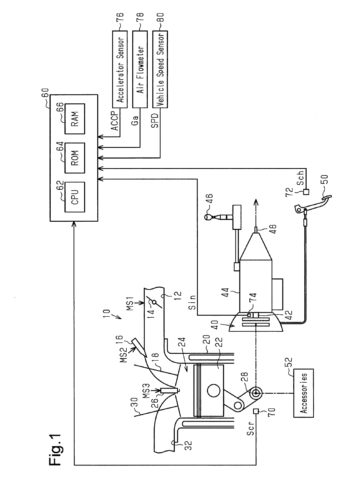
[0032]As shown in FIG. 1, the internal combustion engine 10 includes a throttle valve 14 arranged in an intake passage 12 and a fuel injection valve 16 provided downstream of the throttle valve 14. The fuel injected from the fuel injection valve 16 and the air drawn into the intake passage 12 flow into a combustion chamber 24, which is defined by a cylinder 20 and a piston 22, as an intake valve 18 is opened. The air-fuel mixture drawn into the combustion chamber 24 is burned by the spark discharge of an ignition device 26. The energy generated by combustion is converted into the rotational energy of a crankshaft 28 via the piston 22. The burned air-fuel mixture is discharged to an exhaust passage 32 as exhaust gas when an exhaust valve 30 is opened.

[0033]The crankshaft 28 is connected to an input shaft 42 of a manual transmission 44 via a clutch ...

second embodiment

[0069]A second embodiment will now be described with reference to the drawings. The differences from the first embodiment will mainly be discussed.

[0070]In the present embodiment, when the correction coefficient Kc is gradually decreased toward the feedback operation amount Kfb by setting the assist torque Tas to zero, the gradual decrease rate is set variably in accordance with the vehicle speed SPD.

[0071]FIG. 8 shows the relationship between the vehicle speed SPD and the decrease amount Δ2 according to the present embodiment. As shown in FIG. 8, the decrease amount Δ2 is set to a smaller value when the vehicle speed SPD is low than when the vehicle speed SPD is high in the present embodiment. As a result, the decrease rate of the correction coefficient Kc is smaller when the vehicle speed SPD is low than when the vehicle speed SPD is high. This configuration is aimed at preventing the user from having an impression of insufficient torque by reducing the gradual decrease rate of th...


PUM


Abstract

A controller for an internal combustion engine is configured to control a vehicle internal combustion engine having a crankshaft connected to a manual transmission via a clutch. The controller is configured to execute a feedback process, a torque control process, an assist process, a fixing process, and a gradual decrease process. The fixing process includes fixing a correction coefficient at a specified value on condition that the clutch is in a transition period from the disengaged state to the engaged state. The gradual decrease process includes stopping the fixing process and gradually decreasing the correction coefficient to the feedback operation amount when the fixing process is executed and the assist torque is smaller than or equal to a predetermined value.

Description

CROSS REFERENCE TO RELATED APPLICATION[0001]This application claims priority from Japanese Patent Application No. 2017-184818, filed on Sep. 26, 2017, the disclosure of which is incorporated herein by reference in its entirety.BACKGROUND ART[0002]The present disclosure relates to a controller and control method configured to control a vehicle internal combustion engine of which the crankshaft is connected to a manual transmission via a clutch.[0003]For example, Japanese Laid-Open Patent Publication No. 2014-190178 discloses a controller. The controller calculates a clutch load torque, which is a load torque applied to the crankshaft from the input shaft of the manual transmission through the clutch during a transition period from the clutch disengaged state to the clutch engaged state. The controller also generates a torque request for the internal combustion engine in accordance with the assist torque corresponding to the clutch load torque.SUMMARY[0004]The inventor gave considerat...

Claims


Application Information

Patent Timeline
IPC IPC(8): F02D41/02
CPCF02D41/022F02D41/023F02D29/02F02D41/08F02D2200/1002F02D2200/101F02D2250/18F02D2200/501F02D2200/602
Inventor MORI, JUNICHI
Owner TOYOTA JIDOSHA KK
Why Eureka
Try Eureka