Devices and methods for cosmetic skin resurfacing

a skin resurfacing and cosmetic technology, applied in the field of cosmetic skin resurfacing devices and methods, can solve the problems of limiting the applicability of surgery to certain treatment sites, inconvenient, and expensive, and the method is generally less effective than surgical methods

Active Publication Date: 2019-04-04
CYTRELLIS BIOSYST
View PDF2 Cites 34 Cited by
  • Summary
  • Abstract
  • Description
  • Claims
  • Application Information

AI Technical Summary

Benefits of technology

[0065]By “coring rate” is meant the percentage of hollow needle actuations that result in cored tissue removal from the treatment area out of the total number of hollow needle actuations. The hollow needles of the invention are designed to maximize coring rate and minimize hollow needle actuations that do not result in cored tissue removal. A tissue portion detaches from the skin when the coring force exceeds the tissue resistance force. The tissue resistance force is determined by the connection of the tissue portion to its surrounding tissue. For example, when the hollow needle is fully inserted through the dermal layer of the skin, the tissue resistance force is determined by the connection between the tissue portion in the lumen of the needle and the subcutaneous fat layer. The coring rate is determined by, e.g., the coring force of the hollow needle, the friction between the lumen wall of the hollow needle and the tissue portion, and the tissue resistance force. The coring rate may also be affected by applying a pressure differential across the hollow needle. For example, a vacuum applied at the proximal end of the hollow needle may aspirate the cored tissue portion from the hollow needle, thereby, increasing the coring rate.

Problems solved by technology

Conventional surgical therapies (e.g., a face lift, brow lift, or breast lift) can be effective but are invasive, inconvenient, and expensive, while scarring limits the applicability of surgery to certain treatment sites.
Although minimally invasive methods are available, such methods are generally less effective than surgical methods.
For example, methods using energy sources (e.g., laser, non-coherent light, radiofrequency, and ultrasound) can be effective at improving the architecture and texture of the skin but are less effective at tightening the skin or reducing skin laxity.
In addition, tissue ablative methods that create micro-ablations with photo-thermal energy can generate a coagulation zone in tissue that interferes with closure of the ablation zones, thereby inhibiting tissue tightening.
These methods also require longer patient healing times due to the biological reparative response to coagulated and dead tissue during the remodeling process.
Also, laser ablation depth is typically limited by the depth of the laser beam focus.
Finally, dermal fillers, such as hyaluronic acid, can be injected in the dermal layer to smooth out wrinkles and improve contours, but such fillers do not directly tighten or reduce laxity of the skin.

Method used


Image

  • Devices and methods for cosmetic skin resurfacing
  • Devices and methods for cosmetic skin resurfacing
  • Devices and methods for cosmetic skin resurfacing

Examples


example 1

of Skin Laxity in the Face Using a Hollow Needle with Two Prongs

[0215]An apparatus of the invention may be used to administer treatment to the skin of a subject. Treatment may be performed outside of an operating room environment, thereby minimizing the cost of treatment.

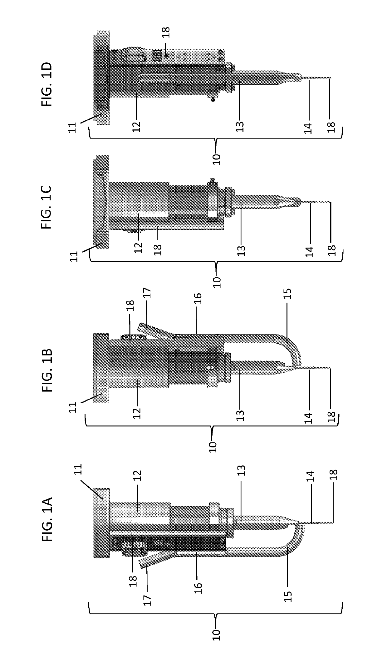
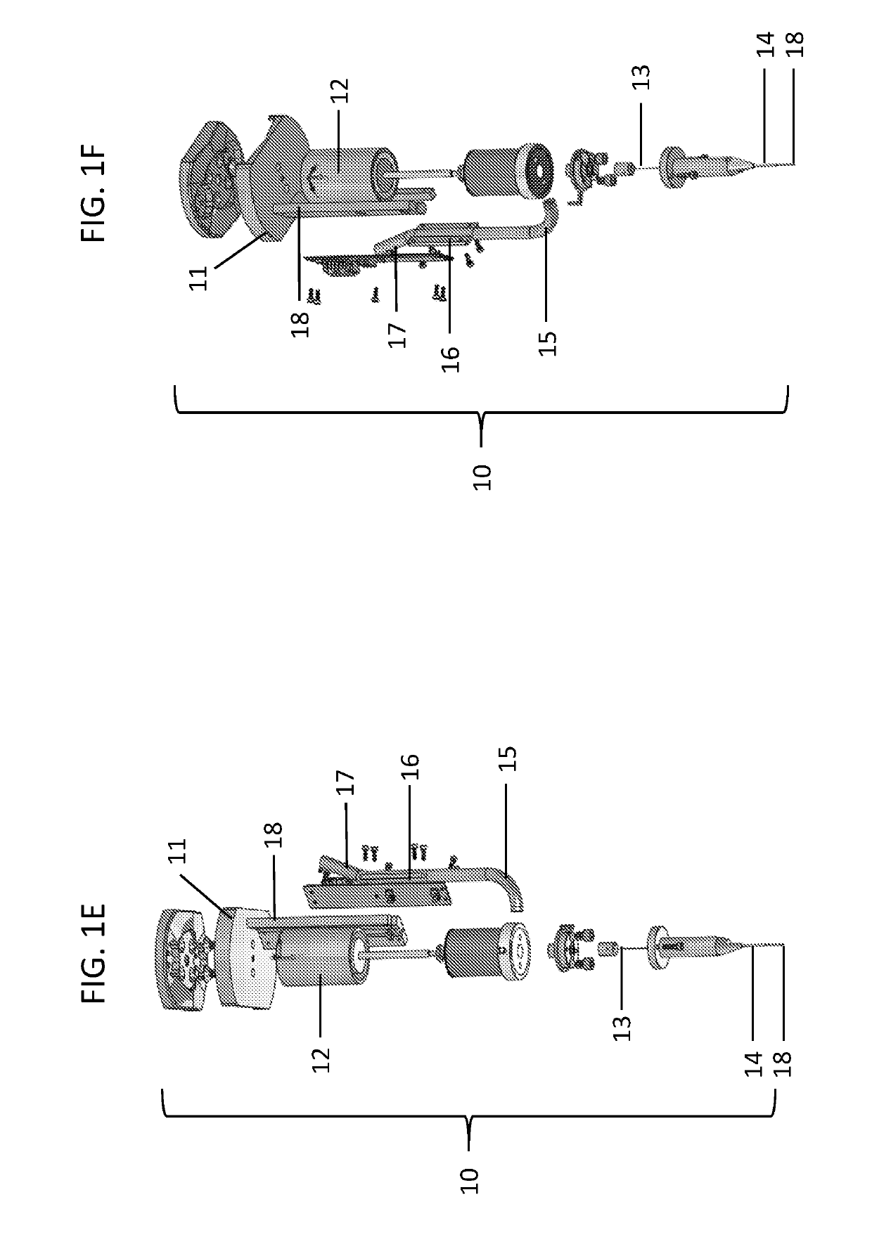
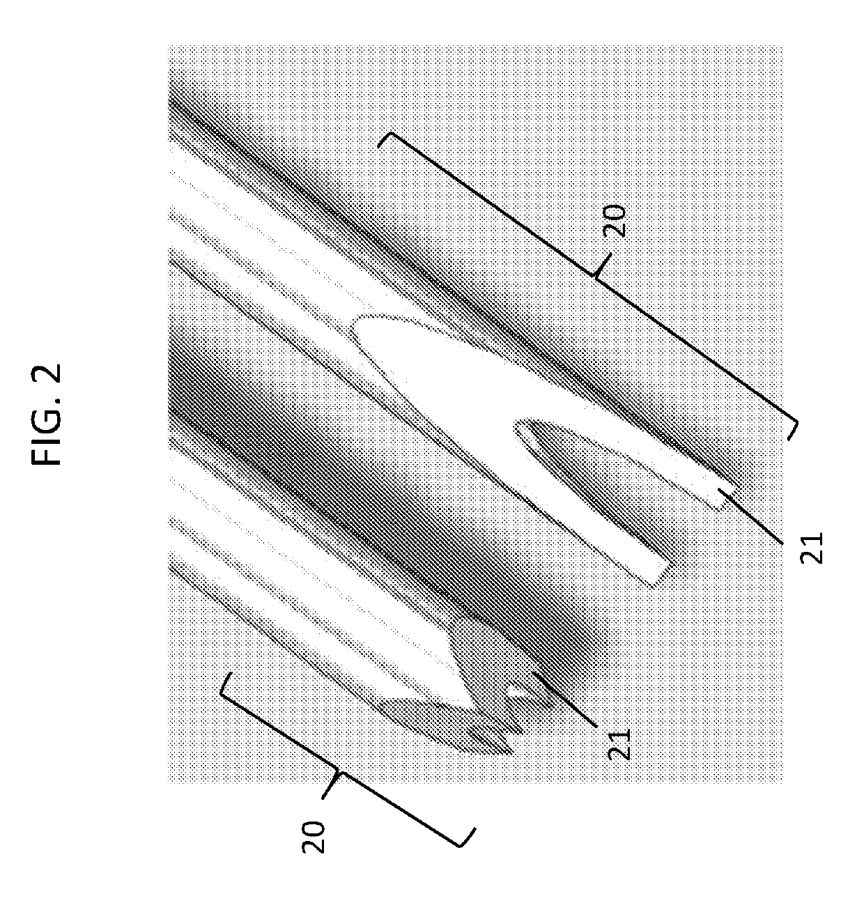
[0216]The apparatus used for treatment of the subject may be any of those described herein. For example, the apparatus may be that shown in any one of FIGS. 16D-16I (e.g., apparatus 163 including actuation unit 151, needle assembly 10, and cover 161). For treatment of skin laxity in the face, a metallic, hollow needle with two prongs each having a bevel angle α of 30 degrees may be selected for application to a treatment area of about 4 mm by about 9 mm. The selected hollow needle may be a 24 gauge needle and may be affixed to the needle assembly of the apparatus at its proximal end (e.g., away from the needle tip). The tip of each prong of the hollow needle may be a sharp point (e.g., sharp point 51 as illustrated ...

example 2

of Skin Laxity in the Face Using a Hollow Needle Having an Edge

[0219]The hollow needle used in Example 1 may be replaced with a hollow needle having an edge. For example, the hollow needle used to treat skin laxity in the face may be a metallic, hollow needle with two prongs each having a bevel angle α of 30 degrees. The hollow needle may be a 24 gauge needle and may be affixed to the needle assembly of the apparatus at its proximal end (e.g., away from the needle tip). The tip of each prong of the hollow needle may be an edge (e.g., edge 52 as illustrated in FIG. 5B). The hollow needle may be configured to penetrate about 0.5 mm to about 2 mm (e.g., about 1 mm) into the skin and to remove an areal fraction of about 0.03 of skin tissue.

example 3

of Skin Laxity in the Face Using a Hollow Needle Having a Flat Tip

[0220]The hollow needle used in Example 1 may be replaced with a hollow needle having a flat tip (e.g., a two dimensional flat tip). For example, the hollow needle used to treat skin laxity in the face may be a metallic, hollow needle with two prongs each having a bevel angle α of 30 degrees. The hollow needle may be a 24 gauge needle and may be affixed to the needle assembly of the apparatus at its proximal end (e.g., away from the needle tip). The tip of each prong of the hollow needle may be a flat tip (e.g., flat tip 53 as illustrated in FIG. 5C). The hollow needle may be configured to penetrate about 0.5 mm to about 2 mm (e.g., about 1 mm) into the skin and to remove an areal fraction of about 0.03 of skin tissue.


PUM


Abstract

Disclosed herein are apparatuses, kits, and methods for treating skin, such as skin tightening, e.g., reducing skin laxity, for treating conditions that would benefit from tissue area or volume reduction, skin restoration, skin tightening, skin lifting, and / or skin repositioning, and / or for generally improving skin function or appearance. Such apparatuses, kits, and methods include one or more hollow needles each having at least one prong and a mechanism for removing skin tissue portion(s) from the hollow needle(s).

Description

CROSS REFERENCE TO RELATED APPLICATIONS[0001]This application claims priority to and the benefit of, and incorporates herein by reference, U.S. provisional Application No. 62 / 314,748, filed Mar. 29, 2016.BACKGROUND OF THE INVENTION[0002]In aesthetic medicine, elimination of excess tissue and / or skin laxity is an important concern that affects more than 25% of the U.S. population. Conventional surgical therapies (e.g., a face lift, brow lift, or breast lift) can be effective but are invasive, inconvenient, and expensive, while scarring limits the applicability of surgery to certain treatment sites.[0003]Although minimally invasive methods are available, such methods are generally less effective than surgical methods. For example, methods using energy sources (e.g., laser, non-coherent light, radiofrequency, and ultrasound) can be effective at improving the architecture and texture of the skin but are less effective at tightening the skin or reducing skin laxity. In addition, tissue a...

Claims


Application Information

Patent Timeline
Patent Type & Authority Applications(United States)
IPC IPC(8): A61B17/34A61B17/3205
CPCA61B17/3417A61B17/32053A61B2017/00761A61B2017/00792A61B2017/320064A61B2017/3454A61B2217/005A61B17/205A61B17/3205A61B17/34
Inventor LEVINSON, DOUGLASGINGGEN, ALECDIMATTEO, KRISTIANBRIK, ROBERTLIZARDI, JOSEANDERSON, NICKBROCKMEIER, OIVIND
Owner CYTRELLIS BIOSYST
Why Eureka
Try Eureka