
Processing system and method for controlling processing machine

a processing system and processing machine technology, applied in the field of processing systems, can solve the problems of deteriorating the working ratio of the whole system, affecting the accuracy of the machining of the processing machine, etc., and achieve the effect of reducing the change in the relative position and reducing the change in the measured relative position

Active Publication Date: 2019-04-04
FANUC LTD
View PDF0 Cites 5 Cited by
  • Summary
  • Abstract
  • Description
  • Claims
  • Application Information

AI Technical Summary

Benefits of technology

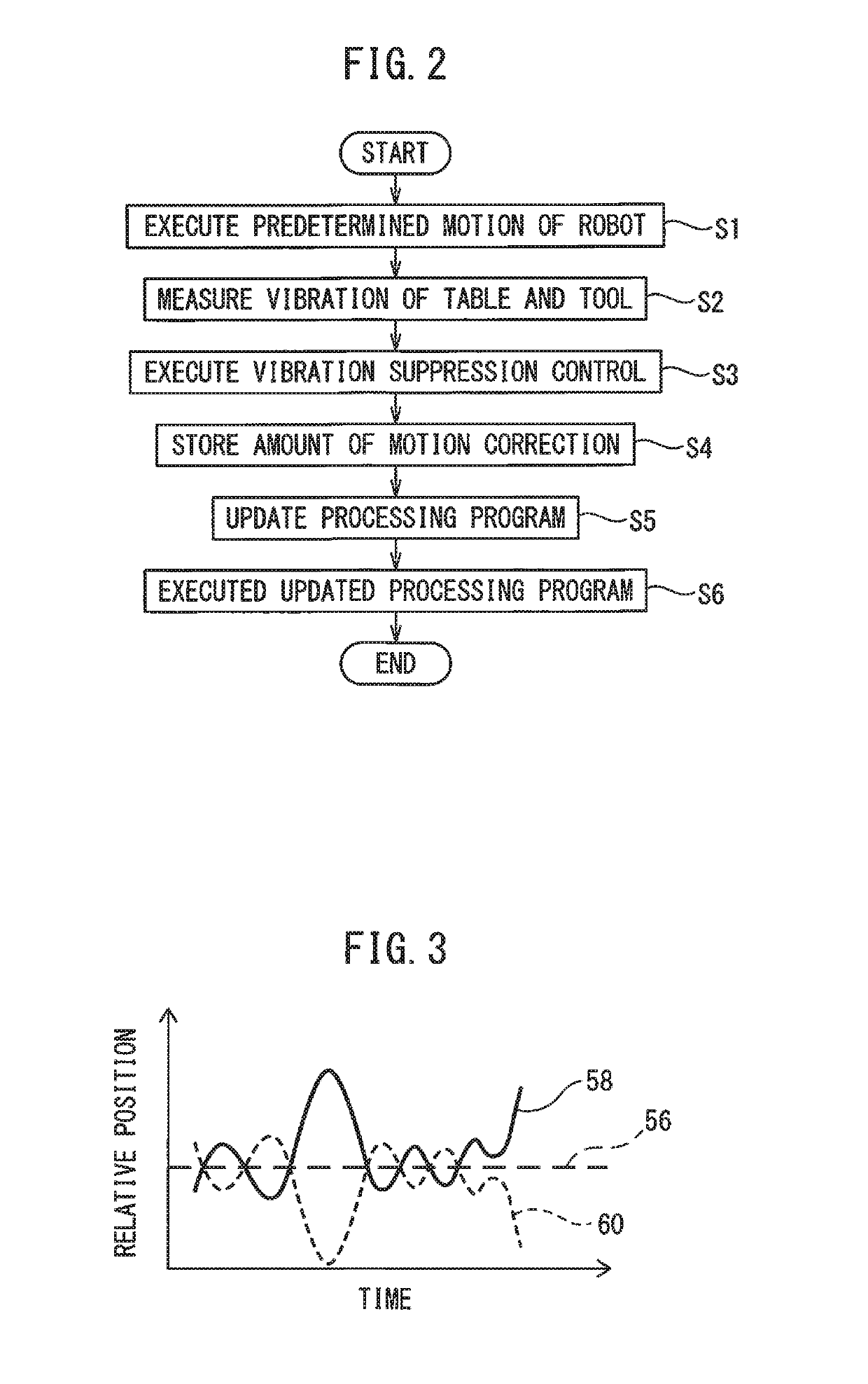
The patent is about a method to control a processing machine that has a part to hold a workpiece and a tool to process the workpiece. The method involves measuring the change in the position of the workpiece and the tool when the machine moves to perform a specific motion. A motion correction is calculated to reduce the change in position and it is stored for later use. When the machine moves to perform the specific motion, the stored motion correction is used to suppress the vibration of the machine while executing the processing program. The technical effect of this patent is to improve the accuracy and stability of processing machines by reducing the vibration caused by the movement of the workpiece and tool.

Problems solved by technology

In such a case, the vibration generated by operating the robot may be transmitted to the processing machine, whereby the machining accuracy of the processing machine may be deteriorated.
However, when the robot is operated as such, a working ratio of the whole system may be deteriorated (i.e., a cycle time of the system may be extended).

Method used


Image

  • Processing system and method for controlling processing machine
  • Processing system and method for controlling processing machine

Examples


Embodiment Construction

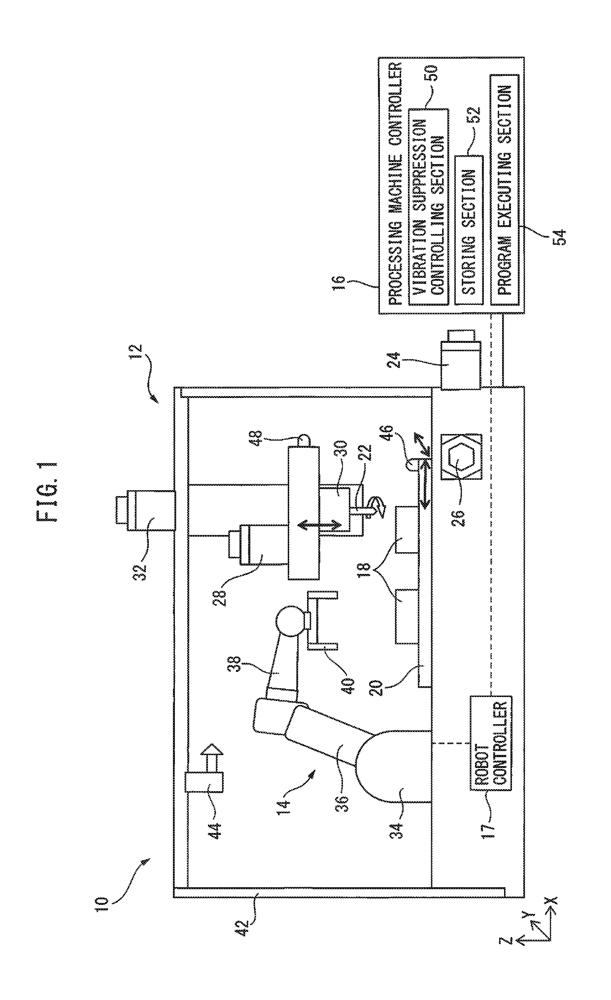
[0011]FIG. 1 shows an example of a configuration of a processing system 10 according to a preferred embodiment. Processing system 10 includes a processing machine 12 such as a machine tool, and a robot 14 positioned within or adjacent processing machine 12. Processing machine 12 is controlled by a processing machine controller 16 connected to processing machine 12, and robot 14 is controlled by a robot controller 17 connected to robot 14. Processing machine controller 16 and robot controller 17 may be separate devices (e.g., computers), each having a CPU and a memory, etc. Otherwise, processing machine controller 16 and robot controller 17 may be constituted as a substantially integrated device (e.g., a computer), having a CPU and a memory, etc.

[0012]Processing machine 12 has a workpiece holding part (in this example, a table) 20, on which an object (or a workpiece) 18 to be processed can be located, or by which workpiece 18 can be held. Processing machine 12 further has a processin...


PUM


Abstract

A processing system and a method for controlling a processing machine of the system, by which the processing accuracy of the processing machine due to the motion of the robot can be prevented from being deteriorated, without reducing the working ratio of the processing system. A processing machine controller has: a vibration suppression controlling section configured to operate at least one of a table and a processing tool, and calculate an amount of motion correction for reducing the change in a relative position between the table and the processing tool measured by vibration sensors respectively arranged on the table and a tool driving part; a storing section configured to store the calculated amount motion correction; and a program executing section configured to, during the robot performs the predetermined motion, execute the processing program while executing vibration suppressing motion based on the stored amount of motion correction.

Description

BACKGROUND OF THE INVENTION1. Field of the Invention[0001]The preset invention relates to a processing system including a processing machine, and a method for controlling the processing machine.2. Description of the Related Art[0002]A robot system having a robot is well-known, in which the robot is positioned within or adjacent a machine tool so that a workpiece can attached to or detached from the machine tool by the root (e.g., JP 2010-036285 A). Further, it is a well-known technique to remove or collect chips or shavings generated from a processing machine by using a robot positioned adjacent the processing machine (e.g., JP 2016-168661 A).[0003]On the other hand, a robot system including a robot is well-known, in which a positional deviation between a gripping part of the robot and an object is detected by an inertial sensor, and the positional relationship between the griping part and the object is adjusted to cancel the positional deviation (e.g., JP 2014-121788 A). Further, a...

Claims


Application Information

Patent Timeline
Patent Type & Authority Applications(United States)
IPC IPC(8): B25J9/16G01H1/00
CPCB25J9/1692G01H1/00B25J9/1694B23Q15/12B23Q17/12G05B19/404G05B2219/39241G05B2219/41122
Inventor TAKIKAWA, RYUJI
Owner FANUC LTD
Learn More