Adaptive network discovery signaling

Active Publication Date: 2019-04-04
SONY CORP
View PDF1 Cites 3 Cited by
  • Summary
  • Abstract
  • Description
  • Claims
  • Application Information

AI Technical Summary

Benefits of technology

The patent describes a method for improving wireless communication by using directional transmissions and signaling to enhance network discovery. The method allows stations to perform network discovery in a distributed mode or a central coordinator mode. The type of signal transmission is determined and transmitted by either the individual station or the central coordinator. The network stations adapt signal transmission to aid in scanning the network. The patent also mentions beamforming, which is a directional transmission that improves received signal power or signal-to-noise ratio at an intended receiver. The technical effects of this patent are improved network discovery and better signal quality.

Problems solved by technology

Existing sub-6 GHz wireless technology is not sufficient to cope with the high demand for data in wireless networks.
High free-space path loss, high penetration, reflection and diffraction losses reduce the available diversity and limit non-line-of-sight (NLOS) communications.
This task is further challenging in mmWave communications due to directional transmissions.
However, existing technologies for mesh networking address mesh discovery solutions for networks operating in broadcast mode, but are not directed for use on networks having directional wireless communications.
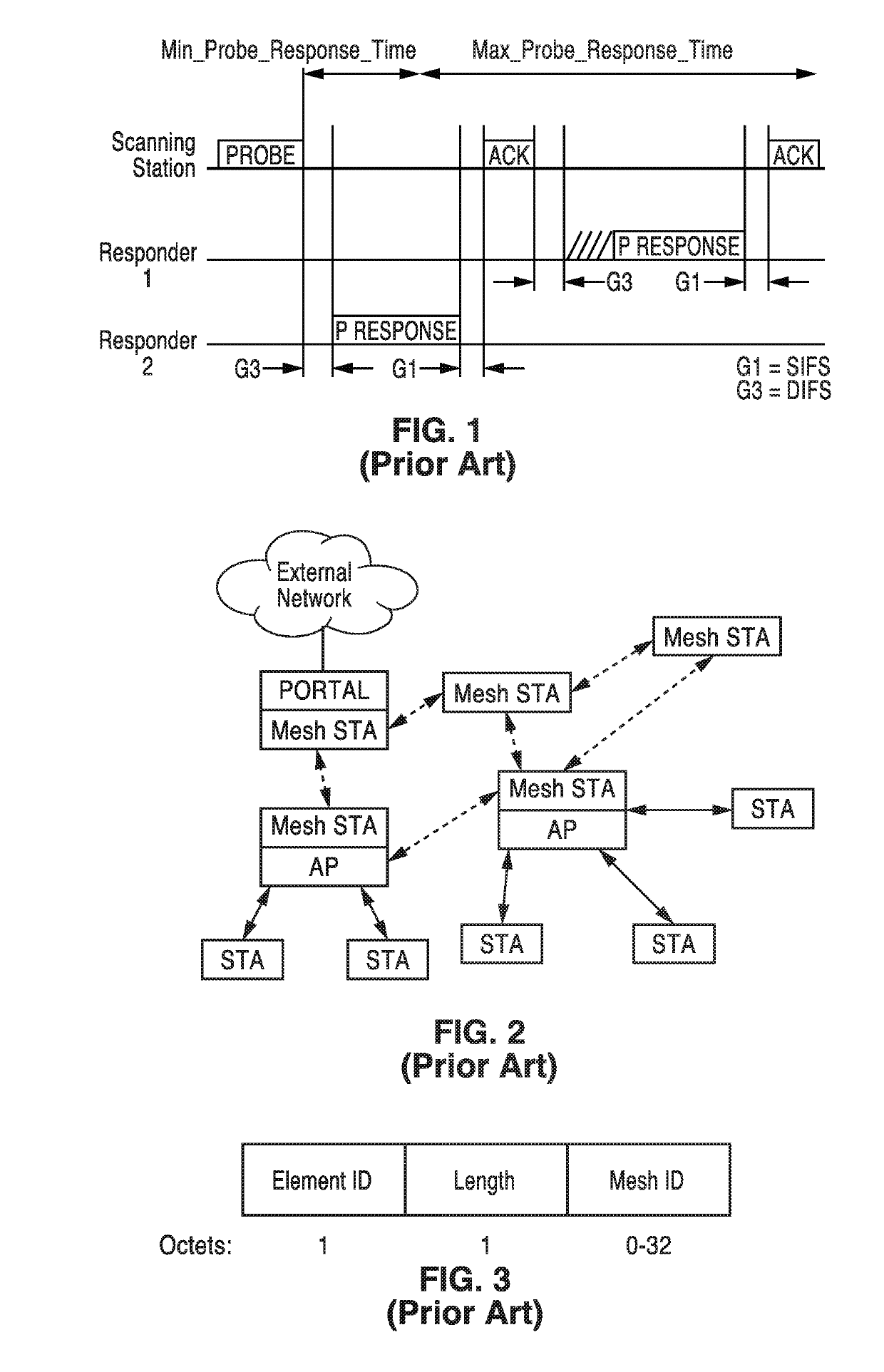
(d) Active scanning can be a source of interference and collision, especially if many new STAs arrive at the same time and are attempting to access the network.
(h) When radio measurement campaigns are active, nodes might not answer the probe requests.
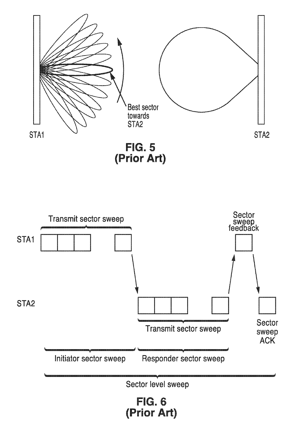
As seen in the problems encountered by prior art communication systems, determination of a proper beam for use requires significant signaling overhead.
If beacons are transmitted less frequently, then beaconing overhead can be decreased, yet it becomes more difficult and slow for a new STA to find an existing network.
The dilemma becomes more problematic when considering forming a mesh network utilizing mmW PHY technology.
Accordingly, all the STAs joining a mesh network should have a capability of beaconing which leads to significant signaling overhead.
Some of the mmWave RF circuitry and antennas may be disabled when the node determines it is unnecessary to communicate with neighbor nodes.
Some of the RF circuitry and antennas may be disabled when the node determines it is unnecessary to communicate with neighbor nodes.
However, as can be seen from the dramatic beam overlapping and signal levels directed at the walls in the figure, this process results in far too many beacon frame transmissions, which will obviously incur not only significant overhead, but also create interference that reduces overall network performance.
Also, it increases beam width of the discovery signal, as the far place from STA-1 is covered by other STAs and STA-1 does not detect a new STA from these areas often.

Method used


Image

  • Adaptive network discovery signaling
  • Adaptive network discovery signaling
  • Adaptive network discovery signaling

Examples


case 1

3.3.1. Distributed Management (Case 1)

[0122]FIG. 16A and FIG. 16B illustrates an example embodiment 130 of overall information exchange among STAs according to a distributed management case according to the present disclosure. In the figure are seen multiple stations 132 in the network, which in this case are depicted as STA-B 134, STA-A 136, STA-6138, STA-5140, STA-3142 and STA-1144. In this section, overall signal flow among STAs are explained. In this example detection of a new STA is the trigger event. It is possible that other types of events can trigger the overall process as explained below.

[0123]With a distributed management procedure, STAs will make autonomous decisions exchanging events that each STA detected and actions that each STAs made. STA-1, STA-3, STA-5, and STA-6 are STAs which were depicted in FIG. 13, and they are transmitting discovery signals, for example beacon frames. STA-A is a new STA that is not a part of the network yet. STA-A 136 shows up at the entranc...

case 2

3.3.2. Centralized Management (Case 2)

[0126]FIG. 17 illustrates an example embodiment 210 of overall information exchange among STAs (STA-A 212, STA-6214, Central Server via STA-2216, STA-1218, STA-3220, and STA-4222), according to a centralized management case according to the present disclosure.

[0127]Similar to the description in the prior section, the network detection of a new STA is considered the trigger event for this example. It should be appreciated, however, that the present disclosure also teaches that other types of events can be utilized to trigger the overall process as later described.

[0128]With a centralized management procedure, STAs report Event Data to a Central Server in the network. In this particular scenario, it is assumed for the sake of example that the Central Server is accessible from STA2 which has a gateway to an external network. Upon reception of the Event Data, the Central Server maintains its database to track events which have occurred on the networ...


PUM


Abstract

An apparatus and method for adaptive network discovery signaling. Information is collected in a database of events, such as the discovery of a new station. The event information (e.g., new station, antenna sectors, active links) is shared with a central coordinator, or other stations in the network. Based on events, at this or other stations, signal transmission forms are adapted, for example for transmitting the beacon signals and notification signals. Adaptations of signal transmission include changing how frequently signaling is performed, timing of signaling, adjusting beam width, and / or adjusting directionality.

Description

CROSS-REFERENCE TO RELATED APPLICATIONS[0001]This application claims priority to, and the benefit of, U.S. provisional patent application Ser. No. 62 / 566,584 filed on Oct. 2, 2017, incorporated herein by reference in its entirety.STATEMENT REGARDING FEDERALLY SPONSORED RESEARCH OR DEVELOPMENT[0002]Not ApplicableINCORPORATION-BY-REFERENCE OF COMPUTER PROGRAM APPENDIX[0003]Not ApplicableNOTICE OF MATERIAL SUBJECT TO COPYRIGHT PROTECTION[0004]A portion of the material in this patent document may be subject to copyright protection under the copyright laws of the United States and of other countries. The owner of the copyright rights has no objection to the facsimile reproduction by anyone of the patent document or the patent disclosure, as it appears in the United States Patent and Trademark Office publicly available file or records, but otherwise reserves all copyright rights whatsoever. The copyright owner does not hereby waive any of its rights to have this patent document maintained...

Claims


Application Information

Patent Timeline
IPC IPC(8): H04W48/16H04W92/20H04W72/04H04L5/00
CPCH04W48/16H04W92/20H04W72/046H04L5/0048H04L41/12H04B7/0617H04B7/0695H04B7/088H04W8/005H04W84/14H04W76/14H04W28/16H04L5/0053H04L5/0091H04W48/12H04W24/02H04W88/04H04B7/06952H04W72/0453H04W84/12
Inventor SAKODA, KAZUYUKIABDALLAH, RAMYABOUELSEOUD, MOHAMED
Owner SONY CORP
Why Eureka
Try Eureka