Method for Modeling Humeral Anatomy and Optimization of Component Design

a humeral anatomy and component design technology, applied in the direction of shoulder joints, instruments, prostheses, etc., can solve the problems of lack of long-term bone ingrowth, catastrophic early component loosening, and the breadth of shoulder surgery complications associated with devices that are not anatomically correct, so as to facilitate and improve joint prosthetic component design, improve the understanding of proximal humeral anatomy, and optimize loading and fit.

Active Publication Date: 2019-04-11
MAYO FOUND FOR MEDICAL EDUCATION & RES
View PDF3 Cites 18 Cited by
  • Summary
  • Abstract
  • Description
  • Claims
  • Application Information

AI Technical Summary

Benefits of technology

[0007]The present invention provides a methodology that improves the understanding of proximal humeral anatomy through the use of CT scan data and 3D modeling. This methodology describes the interaction of anatomical features of the proximal humerus and how these features change based on the specific location in the proximal humerus. Additionally, the methodology has demonstrated that the shape of the proximal humeral region is side specific. Therefore, having right and left specific devices with an anatomic shape in a true population based distribution further facilitates and improves joint prosthetic component design. The methodology can optimize loading and fit at the bone-device interface. Furthermore, models were created to test the methodology and the interaction of the anatomic features and their interdependence on each other. The results of the biomechanical testing validated the methodology demonstrating significantly improved initial fixation compared to currently available standard circular prosthetic component designs. The methodology has also resulted in improved stemless components and fracture stems for joint arthroplasty. The fracture stems include specific features for an improved anatomic fracture fixation device with optimal shape and size of fins to maximize tuberosity healing. Furthermore, cadaveric validation was performed of both the stemless components and fracture stems.

Problems solved by technology

There is a breadth of complications in shoulder surgery associated with devices that are not anatomically correct.
This includes fracturing the humerus when trying to implant a device that is not in the shape of the humeral anatomy, catastrophic early component loosening when contact with native bone is not optimized, as well as lack of long term bone ingrowth.
In addition, a high rate of stress shielding with associated bone resorption has been reported in the literature due to a lack of uniform stress distribution.
In the fracture setting, tuberosity resorption remains a significant problem and has a substantial negative impact on patient outcomes.

Method used


Image

  • Method for Modeling Humeral Anatomy and Optimization of Component Design
  • Method for Modeling Humeral Anatomy and Optimization of Component Design
  • Method for Modeling Humeral Anatomy and Optimization of Component Design

Examples


example

[0119]The following Example has been presented in order to further illustrate the invention and is not intended to limit the invention in any way.

A. Background

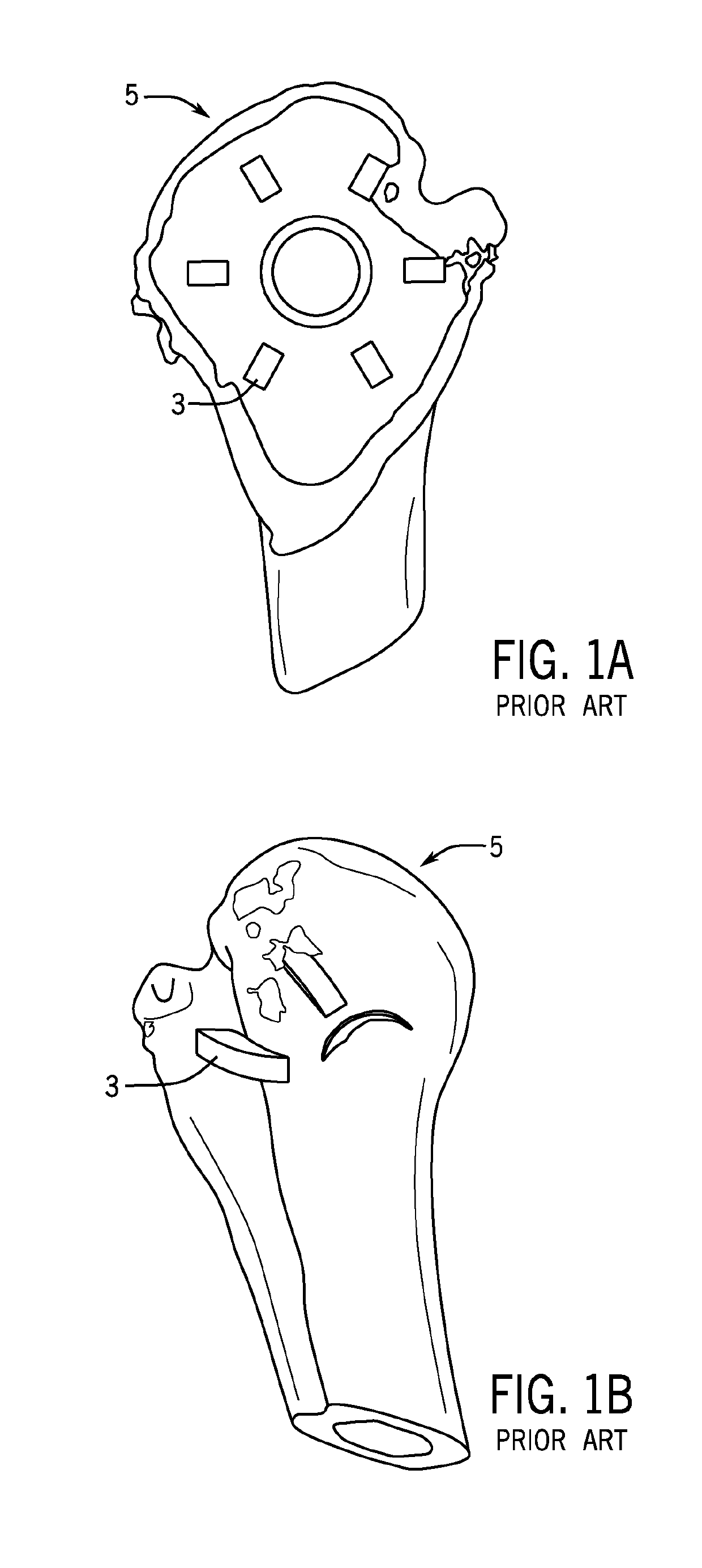
[0120]There has been a drive towards bone preserving and less invasive procedures. However, significant deficiencies have been found in currently available devices, specifically they are not anatomic in shape. Many of the devices used are round with a uniform shape. As devices become smaller to accommodate less invasive procedures and are placed under increased stress at the device bone interface, there has been concern about early catastrophic loosening as well as long term bone ingrowth. In an effort for surgeons to maximize contact with native bone, there is a growing tendency for intra-operative fractures due to surgeons forcing a non-anatomic device in an anatomic space or placing an implant that penetrates the cortical bone creating a substantial risk of a stress riser with increased risk of future fracture.

[0121]In orde...


PUM

PropertyMeasurementUnit
heightaaaaaaaaaa
widthaaaaaaaaaa
angleaaaaaaaaaa

Abstract

Stemless components and fracture stems for joint arthroplasty, such as shoulder arthroplasty, are disclosed. Also, methods and devices are disclosed for the optimization of shoulder arthroplasty component design through the use of medical imaging data, such as computed tomography scan data.

Description

CROSS-REFERENCES TO RELATED APPLICATIONS[0001]This application is a continuation application of PCT International Application No. PCT / US18 / 24044 having an international filing date of Mar. 23, 2018 which claims priority to U.S. Patent Application No. 62 / 476,214 filed Mar. 24, 2017.STATEMENT REGARDING FEDERALLY SPONSORED RESEARCH[0002]Not Applicable.BACKGROUND OF THE INVENTION1. Field of the Invention[0003]The invention relates to methods for the optimization of joint arthroplasty component design and shoulder arthroplasty components such as stemless components and fracture stems for joint arthroplasty.2. Description of the Related Art[0004]Various prostheses for the replacement of the shoulder joint are known. In one example shoulder prosthesis, the upper portion of the humerus is replaced by a humeral component including (i) a stem, or cleat, that extends into a bore formed within the humerus and (ii) a generally hemispherical head portion that is connected to the stem. The hemisph...

Claims


Application Information

Patent Timeline
Patent Type & Authority Applications(United States)
IPC IPC(8): A61F2/40A61F2/30G16H30/20
CPCA61F2/4059A61F2/30771A61F2/30942G16H30/20A61F2002/30884A61F2002/30784A61F2002/30604A61F2002/3093A61F2002/30948A61F2002/30945A61F2002/30963B33Y80/00A61F2/4003A61F2002/30171A61F2002/30332A61F2002/30616A61F2002/4007A61F2002/4062A61F2002/4066Y02P10/25B22F10/20A61F2002/30943
Inventor SPERLING, JOHN W.
Owner MAYO FOUND FOR MEDICAL EDUCATION & RES
Why Eureka
Try Eureka