Ferromagnetic material sputtering target

a ferromagnetic material and target technology, applied in the field of magnetized material sputtering target, can solve the problems of difficult to realize such a structure, inability to generalize, and uneven composition of the alloy base of the target, and achieve the effects of reducing the generation of particles during sputtering, improving the characteristics of suppression of abnormal discharge, and excellent cost improvement

Active Publication Date: 2019-04-11
JX NIPPON MINING& METALS CORP
View PDF4 Cites 1 Cited by
  • Summary
  • Abstract
  • Description
  • Claims
  • Application Information

AI Technical Summary

Benefits of technology

[0024]According to the present invention, a ferromagnetic material sintered sputtering target of a non-magnetic material grain-dispersed type can improve characteristics regarding suppression of abnormal discharge caused by oxides and reduction of generation of particles during sputtering more considerably than before. This will demonstrate an excellent cost improvement effect by further improving yields.

Problems solved by technology

Which method is used to produce sputtering targets depends on the required sputtering characteristics and thin film performance, and thus cannot be generally determined.
The reason for this is that for sputtering targets for use in the formation of perpendicular magnetic recording-type recording layers, it is necessary to uniformly disperse inorganic grains in an alloy base, and it is difficult to realize such a structure by the dissolution method.
However, the presence of the alloy of specific composition as coarse grains in the alloy base of the sputtering target simultaneously means that composition unevenness is locally present in the alloy base of the target.
Thus there was a concern that the uniformity of the composition of a thin film obtained by sputtering such a target would be affected not a small extent.
With these targets, the oxide as a dispersing element is an insulator, so the oxide can be a cause of abnormal discharge depending on the shape and dispersed form.
In addition, there was a problem in that abnormal discharge, drop-outs of the oxide, etc., caused generation of particles during sputtering.
Accordingly, requirements for the size and number of particles allowable on magnetic recording media are becoming increasingly severe.

Method used


Image

  • Ferromagnetic material sputtering target
  • Ferromagnetic material sputtering target

Examples


example 1

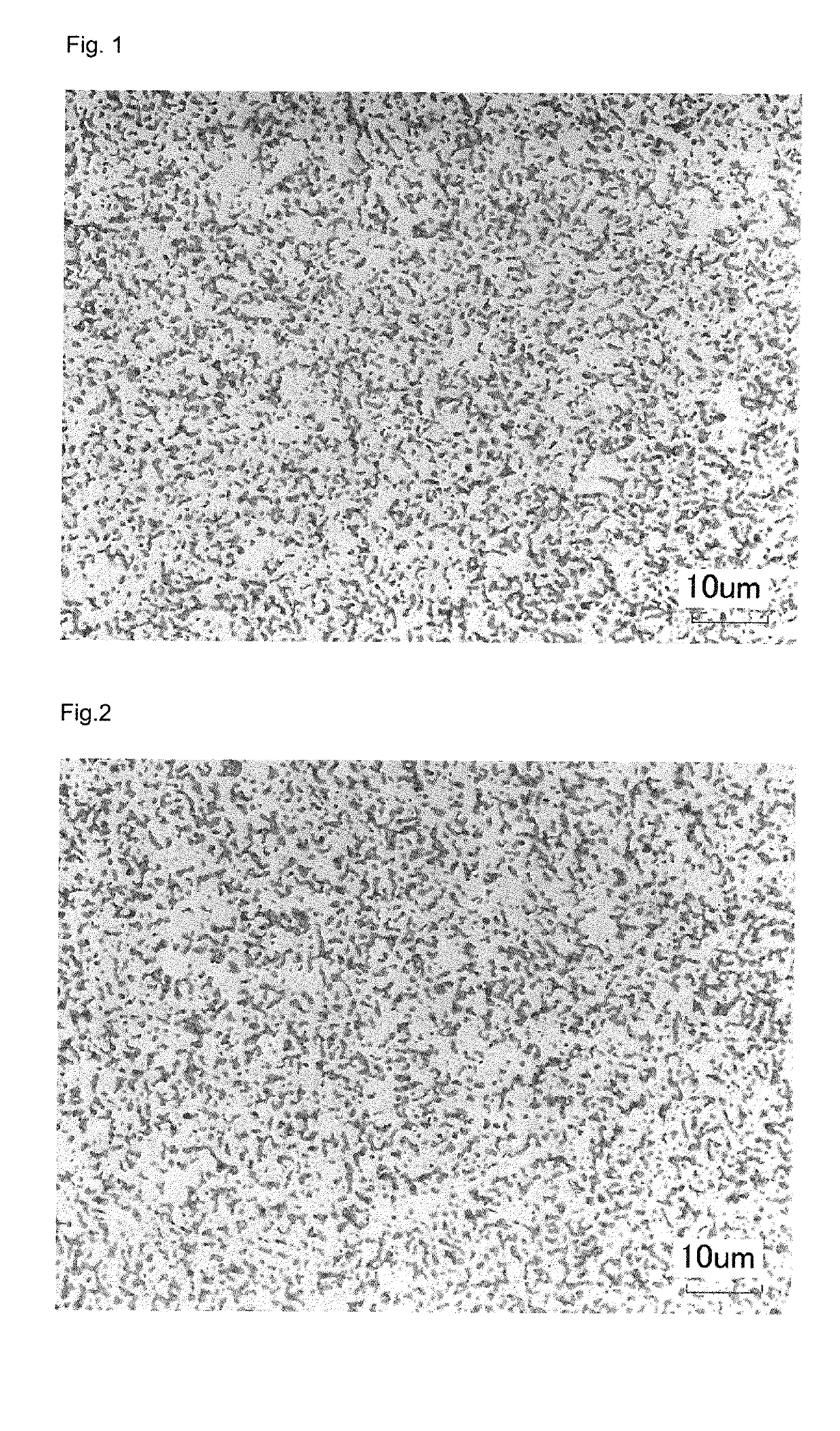
[0054]As metal component raw material powders, a Co powder having an average grain diameter of 3 μm and a Pt powder having an average grain diameter of 3 μm; and as oxide component raw material powders, a TiO2 powder having an average grain diameter of 1 μm, a SiO2 powder having an average grain diameter of 1 μm, and a CoO powder having an average grain diameter of 1 μm were prepared. These powders were weighed at a certain molar ratio. The composition is as follows.

Composition: 80Co-5Pt-5TiO2-5SiO2-5CoO (mol %)

[0055]Next, the three oxide powders, i.e., TiO2 powder, SiO2 powder, and CoO powder, which were oxide component raw material powders, were mixed, and pre-heat treatment was performed on the resulting powder mixture. The pre-heat treatment was performed in atmospheric air at ordinary pressure at 1050° C. for 300 minutes. The oxide raw material powder mixture after the completion of pre-heat treatment was cooled down to room temperature by furnace cooling, and then subjected to...

example 2

[0063]The preparation and weighing of raw material powders were performed in the same manner as in Example 1, and the composition was also the same as that of Example 1.

[0064]In Example 2, two (i.e., TiO2 powder and SiO2 powder) of the three oxide component raw material powders, i.e., TiO2 powder, SiO2 powder, and CoO powder, were mixed, and pre-heat treatment was performed on the resulting powder mixture. The pre-heat treatment was performed in atmospheric air at ordinary pressure at 1050° C. for 300 minutes. The oxide raw material powder mixture after the completion of pre-heat treatment was once cooled to room temperature by furnace cooling, and then was subjected to the subsequent step.

[0065]The oxide component raw material powder mixture, which had been subjected to the above pre-heat treatment, and the metal component raw material powders, which had not been subjected to heat treatment, were mixed and pulverized for 10 minutes using a planetary-motion mixer having a ball capac...

example 3

[0068]As metal component raw material powders, a Co powder having an average grain diameter of 3 μm, a Cr powder having an average grain diameter of 3 μm, and a Pt powder having an average grain diameter of 3 μm; and as oxide component raw material powders, a TiO2 powder having an average grain diameter of 1 μm and a SiO2 powder having an average grain diameter of 1 μm were prepared. These powders were weighed at a certain molar ratio. The composition is as follows.

Composition: 50Co-10Cr-25Pt-5TiO2-10SiO2 (mol %)

[0069]Next, the two oxide powders, i.e., TiO2 powder and SiO2 powder, which were oxide component raw material powders, were mixed, and pre-heat treatment was performed on the resulting powder mixture. The pre-heat treatment was performed in atmospheric air at ordinary pressure at 1050° C. for 300 minutes. The oxide raw material powder mixture after the completion of pre-heat treatment was cooled down to room temperature by furnace cooling, then was subjected to the subsequen...


PUM

PropertyMeasurementUnit
grain diameteraaaaaaaaaa

Abstract

Provided is an oxide grain-dispersed ferromagnetic material sputtering target having a fine structure which can effectively reduce abnormal discharge and generation of particles caused by oxide grains. A sintered sputtering target contains, as metal or an alloy, 0 mol % or more and 45 mol % or less of Pt, 55 mol % or more and 95 mol % or less of Co, and 0 mol % or more and 40 mol % or less of Cr; and further contains at least two kinds of oxides. The oxides are present in the metal or alloy, and the standard deviation of the number density of oxides is 2.5 or less.

Description

TECHNICAL FIELD[0001]The present invention relates to a magnetic material sputtering target used for the formation of magnetic thin films for use in recording layers etc. of magnetic recording media, particularly granular films of magnetic recording media of hard disks employing a perpendicular magnetic recording system. Specifically, the present invention relates to a sintered sputtering target comprising a non-magnetic material grain-dispersed magnetic material in which the dispersion properties of oxides in the target are improved so as to suppress abnormal discharge and prevent generation of particles during sputtering, and it also relates to a method for producing the same.BACKGROUND ART[0002]In magnetic recording media, such as hard disks, layers obtained by forming a thin film of a magnetic material on a substrate such as glass are used as magnetic recording layers. For the formation of such magnetic recording layers, a magnetron sputtering method using a direct current (DC) ...

Claims


Application Information

Patent Timeline
Patent Type & Authority Applications(United States)
IPC IPC(8): C23C14/34C22C19/07
CPCC23C14/3414C22C19/07C23C14/0688C23C14/35
Inventor FURUYA, YUKI
Owner JX NIPPON MINING& METALS CORP
Why Eureka
Try Eureka