
Display panel and gate signal control method for display panel

a display panel and gate signal technology, applied in the direction of electronic switching, pulse technique, instruments, etc., can solve the problems of large difference between distant resistance and close resistance, parasitic capacitance, parasitic resistance, etc., and achieve the effect of improving the difference of gate signals

Inactive Publication Date: 2019-04-18
SHENZHEN CHINA STAR OPTOELECTRONICS SEMICON DISPLAY TECH CO LTD
View PDF1 Cites 0 Cited by
  • Summary
  • Abstract
  • Description
  • Claims
  • Application Information

AI Technical Summary

Benefits of technology

The patent describes a display panel and a method for controlling gate signals to improve consistency in the signals between different parts of the panel. This results in better color accuracy and consistent brightness levels, making the display more reliable and high-quality.

Problems solved by technology

However, this method may cause parasitic resistance and parasitic capacitance in the IC.
Difference between the distant resistance and close resistance is particularly large.
This situation may cause a huge difference between the distant and close gate signals in the panel.

Method used


Image

  • Display panel and gate signal control method for display panel
  • Display panel and gate signal control method for display panel
  • Display panel and gate signal control method for display panel

Examples


Embodiment Construction

[0091]To further illustrate the technical means adopted by the present invention and the effects thereof, the following describes the preferable embodiments of the present invention and the accompanying drawings in detail. Obviously, the described embodiments are only a part but not all of the embodiments of the present invention. All other embodiments obtained by persons of ordinary skill in the art based on the embodiments of the present invention without creative efforts shall fall within the protection scope of the present invention.

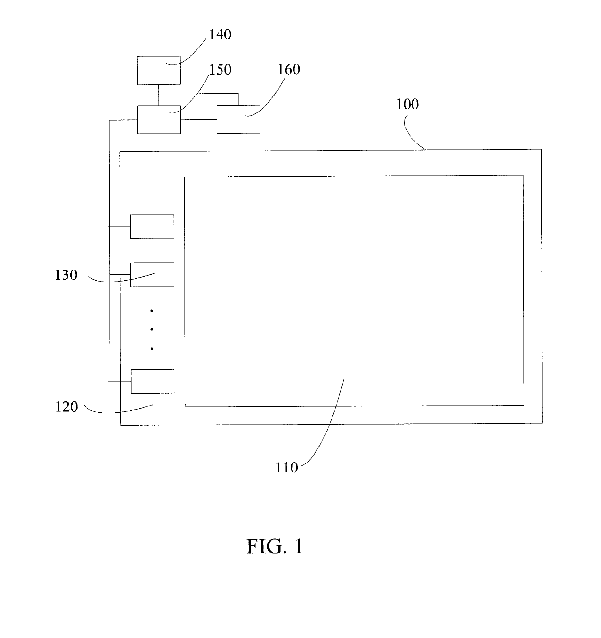
[0092]Please refer to FIG. 1. The present disclosure provides a display panel which includes a gate driving substrate 100, a plurality of gate driving units 130, a level shifter 140, a driving circuit 150, and voltage control circuit 160.

[0093]The gate driving substrate 100 includes a pixel array 110 and a circuit laying area 120 which is disposed near the pixel array. The pixel array 110 includes a plurality of rows of pixel units. The plurality of ...


PUM


Abstract

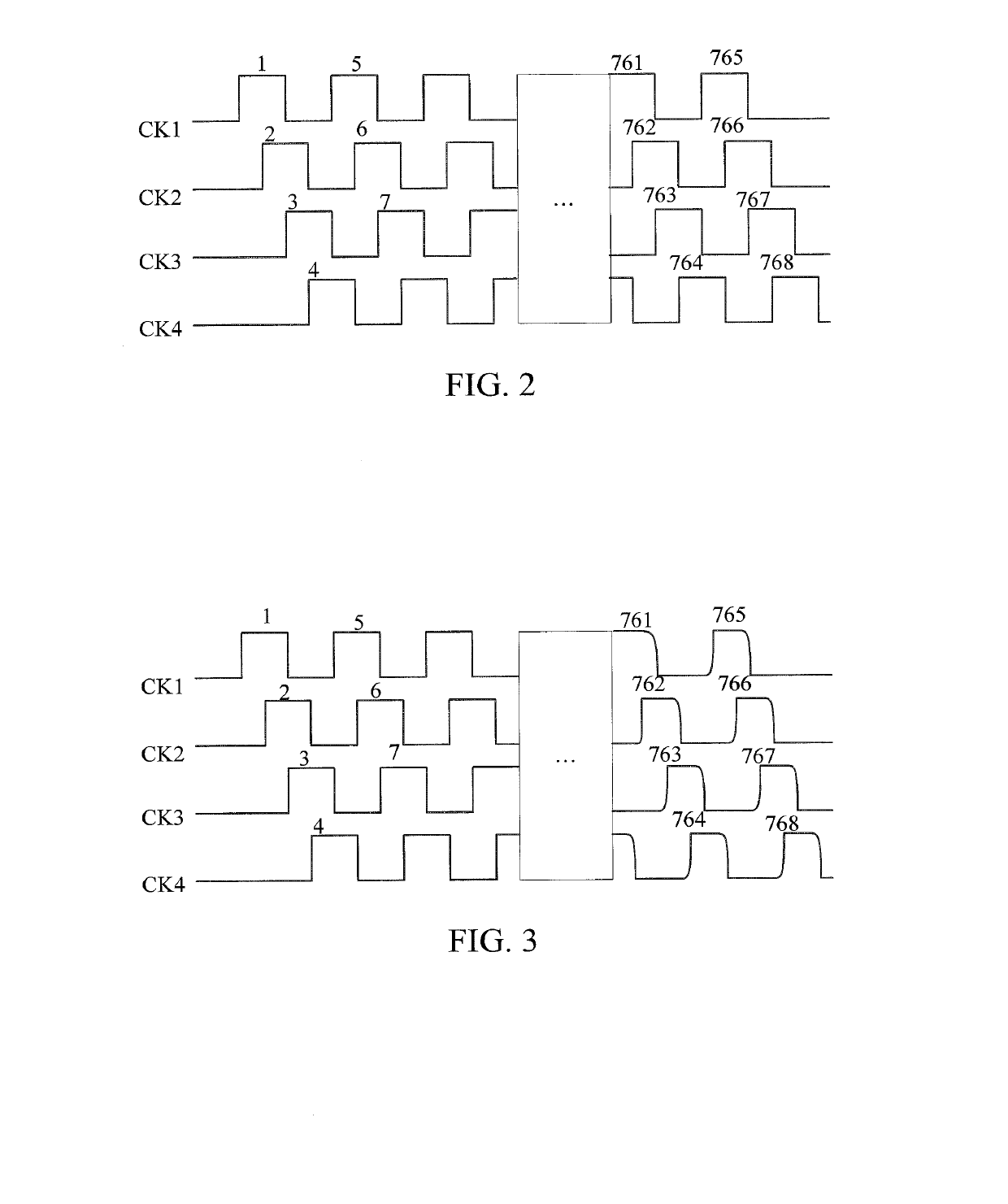
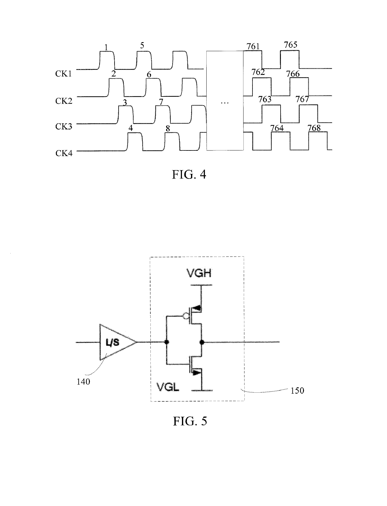
The present disclosure provides a display panel and a gate signal control method for the display panel. The display panel includes a gate driving substrate, a plurality of gate driving units, a level shifter, and a driving circuit. A control end of the driving circuit is coupled to an output end of the level shifter. An output end of the voltage control circuit is coupled to an input end of the driving circuit. The voltage control circuit is configured to set different output voltages applied to the pixel units to correspond to the signals outputted from the driving circuit, for making on and off frequencies of the input end and the output end of the driving circuit increase row by row.

Description

FIELD OF INVENTION[0001]The present disclosure relates to the field of liquid crystal displays, and more particularly to a GOA driving circuit and a liquid display panel.BACKGROUND OF INVENTION[0002]Present display panels include liquid crystal display (LCD) panels and organic light emitting display (OLED) panels. OLED display panels have become the display devices having the highest developmental potential due to their advantages, such as self-illumination, low driving voltage, high illumination efficiency, short response times, high definition and high contrast, nearly 180 degree viewing angle, wide operating temperatures, flexible display, large full-color display area, etc.[0003]Gate on array (GOA) utilize thin film transistors (TFTs) in the TFT-LCD and level shifters (level shifter ICs) on a circuit board to generate required gate signals. This method can efficiently reduce number of gate ICs and reduce costs.[0004]However, this method may cause parasitic resistance and parasit...

Claims


Application Information

Patent Timeline
Patent Type & Authority Applications(United States)
IPC IPC(8): G09G3/36
CPCG09G3/3677G09G2310/06G09G2310/0289G09G2310/027H03K19/017509H03K17/6872G09G3/3674G09G2320/0223G09G2310/0291
Inventor ZHANG, XIANMING
Owner SHENZHEN CHINA STAR OPTOELECTRONICS SEMICON DISPLAY TECH CO LTD
Learn More