Eureka AIR delivers breakthrough ideas for toughest innovation challenges, trusted by R&D personnel around the world.

Polishing apparatus

Active Publication Date: 2019-04-25
EBARA CORP
View PDF0 Cites 0 Cited by
  • Summary
  • Abstract
  • Description
  • Claims
  • Application Information

AI Technical Summary

Benefits of technology

The patent text describes a polishing apparatus that allows for easy replacement of a light source with another type of light source. The apparatus uses a light-source module that can be easily detached and attached to the base, while the base remains fixed to the polishing table. This allows for easy replacement of the light-source module without needing to disconnect the light-emitting transmission line from the base. The light-emitting transmission line is coupled to the base, and the position of the connection end of the light-emitting transmission line relative to the base is fixed at all times. This ensures accurate film-thickness measurement and eliminates the need to change the quantity of light when the light-source module is replaced.

Problems solved by technology

However, there is no light source that can cover such a wide wavelength range.
However, since a light source is disposed on a polishing table of a polishing apparatus, there may be no space large enough to arrange a plurality of light sources on the polishing table.

Method used


Image

  • Polishing apparatus
  • Polishing apparatus
  • Polishing apparatus

Examples


Embodiment Construction

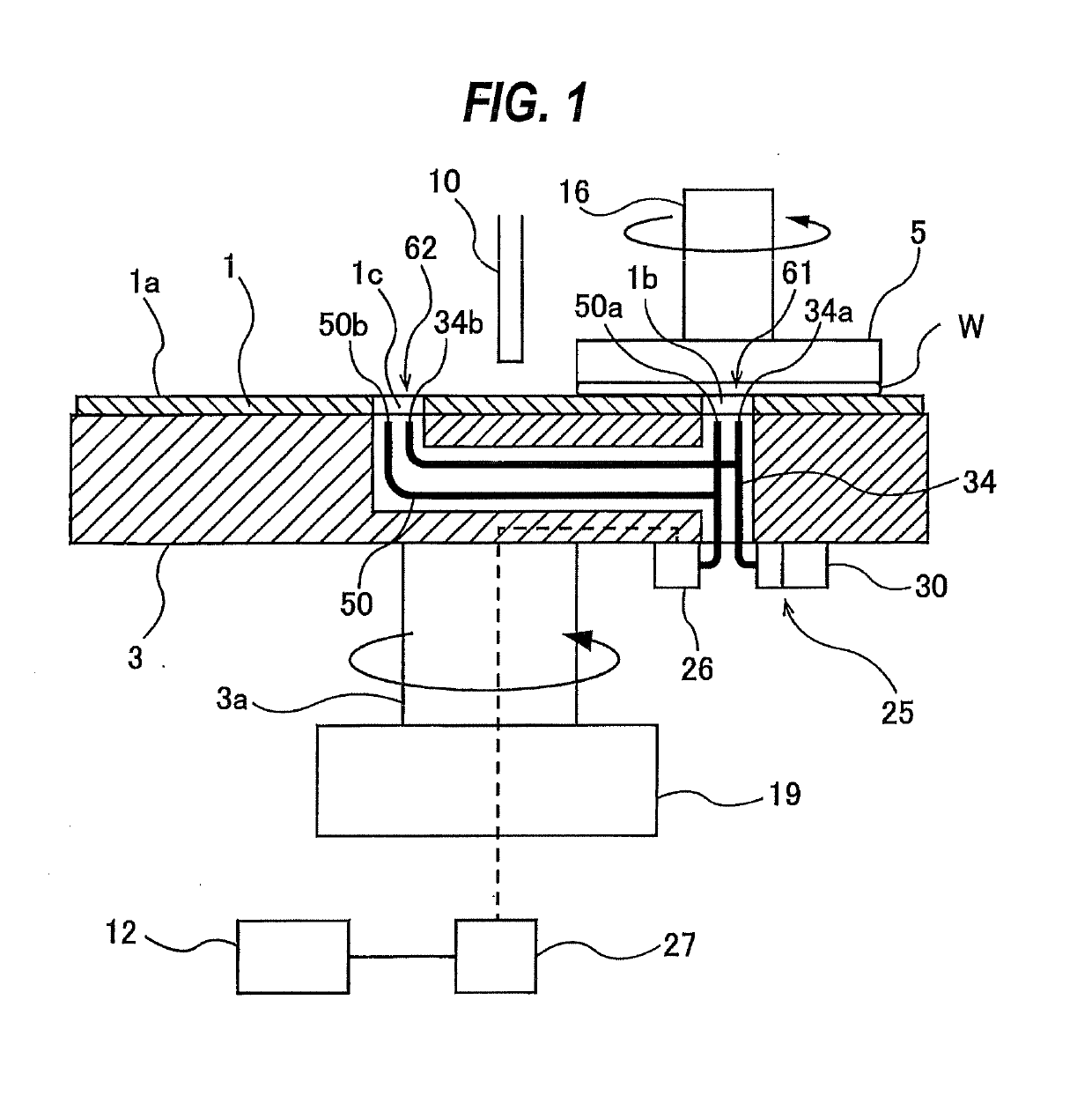
[0028]Embodiments will be described below with reference to the drawings. FIG. 1 is a view showing an embodiment of a polishing apparatus. As shown in FIG. 1, the polishing apparatus includes a polishing table 3 supporting a polishing pad 1, a polishing head 5 for holding a wafer W and pressing the wafer W against the polishing pad 1 on the polishing table 3, a polishing-liquid supply nozzle 10 for supplying a polishing liquid (e.g., slurry) onto the polishing pad 1, and a polishing controller 12 for controlling polishing of the wafer W.

[0029]The polishing table 3 is coupled to a table motor 19 through a table shaft 3a, so that the polishing table 3 is rotated by the table motor 19 in a direction indicated by arrow. The table motor 19 is located below the polishing table 3. The polishing pad 1 is attached to an upper surface of the polishing table 3. The polishing pad 1 has an upper surface, which provides a polishing surface 1a for polishing the wafer W. The polishing head 5 is sec...


PUM


Abstract

There is disclosed a polishing apparatus which allows for easy replacement of a light source with another type of light source. The light-source assembly includes: a base fixed to a polishing table and coupled to a light-emitting transmission line; and a light-source module having a lamp for emitting light. The light-source module is removably attached to the base. The base is a common base which is adapted to any of a plurality of light-source modules of different types including the light-source module. The base includes a positioning structure which achieves positioning of the light-source module relative to the base.

Description

CROSS REFERENCE TO RELATED APPLICATION[0001]This document claims priority to Japanese Patent Application Number 2017-202848 filed Oct. 19, 2017, the entire contents of which are hereby incorporated by reference.BACKGROUND[0002]Manufacturing processes of semiconductor devices include a process of polishing a dielectric film, e.g., SiO2, and a process of polishing a metal film, e.g., copper or tungsten. Manufacturing processes of backside illumination CMOS sensor and through-silicon via (TSV) include a process of polishing a silicon layer (silicon wafer), in addition to the polishing processes of the dielectric film and the metal film. Polishing of a wafer is terminated when a thickness of a film (e.g., the dielectric film, the metal film, or the silicon layer), constituting a wafer surface, has reached a predetermined target value.[0003]Polishing of a wafer is carried out using a polishing apparatus. In order to measure a film thickness of a non-metal film, such as a dielectric film ...

Claims


Application Information

Patent Timeline
IPC IPC(8): B24B37/013B24B37/10B24B49/12G01J3/42G01J3/10
CPCB24B37/013B24B37/10B24B49/12G01J3/42G01J3/10B24B37/107B24B37/205G01J3/0291G01N21/9501G01J3/0218G01N21/8422G01B11/0633
Inventor TAKAHASHI, NOBUYUKIKIMBA, TOSHIFUMIKINOSHITA, MASAKI
Owner EBARA CORP
Why Eureka
Eureka Blog
Learn More