Compact pseudorandom scale and read head for an inductive type absolute position encoder

an absolute position encoder and pseudorandom code technology, applied in the field of precision measurement instruments, can solve the problems of complex readhead signal processing, unsuitable or ideal for all applications, and the known techniques of implementing binary serial code tracks (e.g., pseudorandom code tracks) in absolute encoders, etc., to reduce detector dimensions and/or code bit processing complexity.

Active Publication Date: 2019-04-25
MITUTOYO CORP
View PDF0 Cites 9 Cited by
  • Summary
  • Abstract
  • Description
  • Claims
  • Application Information

AI Technical Summary

Benefits of technology

[0017]An absolute encoder system wherein Wcode is larger than Wf is unusual in pseudorandom code type absolute encoders, and particularly unusual in relation to magnetic or inductive type absolute encoders. As indicated previously, Wcode is typically equal to or smaller than the periodic wavelength Wf of the incremental track, to avoid the position ambiguity problem outlined above. However, according to principles disclosed herein, the position ambiguity problem is overcome when Wcode is larger than Wf by analyzing the signals provided by the M sets of code pattern sensing elements to determine the code position relative to the detector with a resolution that is b

Problems solved by technology

Otherwise, operation may not be reliable under all circumstances, or undesirably complex readhead signal processing may be required, or the like.
However, the k

Method used


Image

  • Compact pseudorandom scale and read head for an inductive type absolute position encoder
  • Compact pseudorandom scale and read head for an inductive type absolute position encoder
  • Compact pseudorandom scale and read head for an inductive type absolute position encoder

Examples


Embodiment Construction

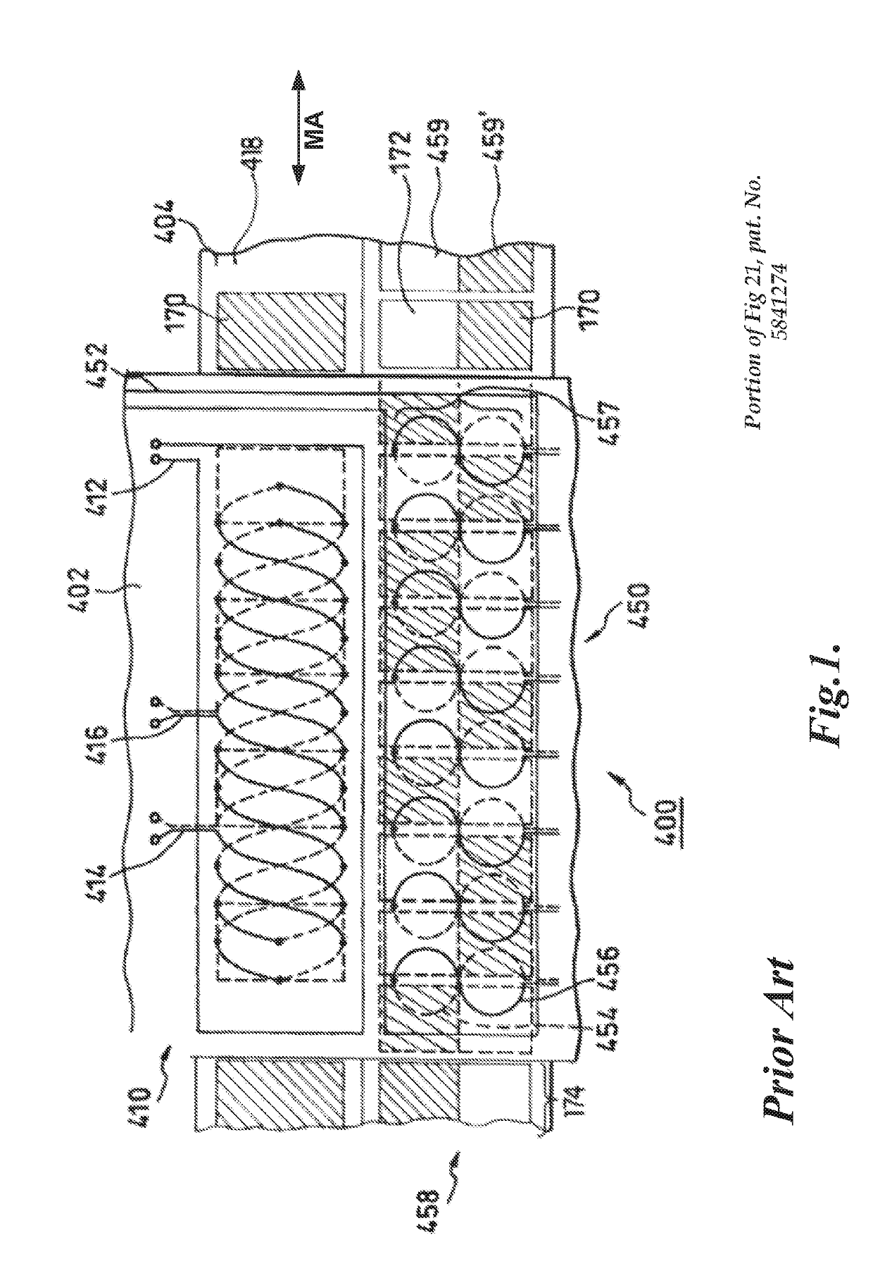
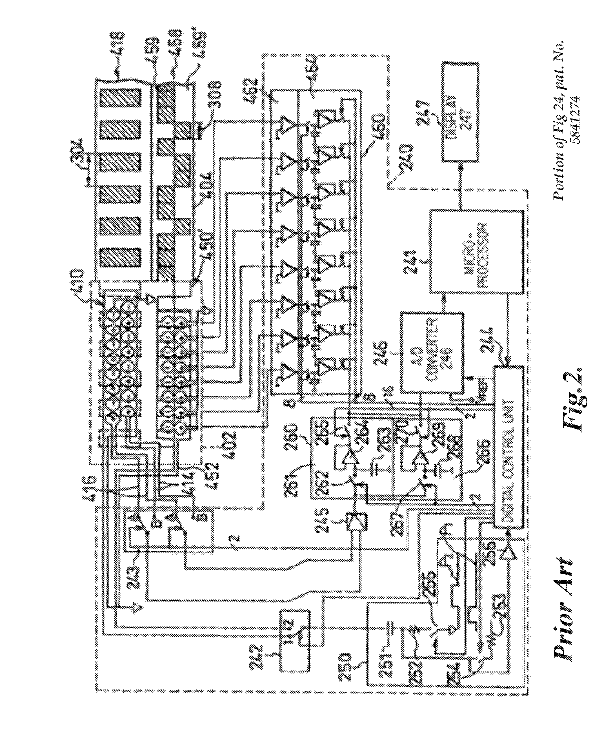
[0024]FIGS. 1 and 2 are diagrams including portions of a known inductive-type absolute encoder system 400 that uses a first known code sensing configuration. The diagrams of FIGS. 1 and 2 are disclosed in the previously incorporated U.S. Pat. No. 5,841,274 (the '274 patent). In various implementations, according to principles disclosed herein, the sensing principles and signal processing taught in the '274 patent may be used in combination with principles disclosed herein. Various aspects of the absolute encoder system 400 will be briefly summarized here. Additional associated details, explanation, and teachings are available in the '274 patent.

[0025]The encoder system 400 includes a readhead 402 (which includes a detector comprising a field generator and sensing elements described below) which is mounted proximate to a scale 404, with relative motion between the detector and scale along a measuring axis direction MA. The scale 404 extends along the measuring axis direction MA, and ...


PUM


Abstract

An absolute position encoder comprises a scale and a detector overlaying the scale. The scale includes a periodic pattern of wavelength Wf and a code pattern having bit length Wcode. The detector includes a set of periodic pattern sensors and M sets of code pattern sensors. M is at least two. The configuration principles include: a) Wcode is larger than Wf and at most M*Wf, and b) the sets of code pattern sensors are located along the measuring axis at respective alignment positions configured such that as the code pattern moves in a single direction it moves by successive alignment intervals that are each at most Wf to align with successive alignment positions. Signal processing is provided to determine the absolute position based on the M respective sets of code detector signals and on spatially periodic signals arising in the periodic pattern sensing elements due to the periodic pattern.

Description

BACKGROUNDTechnical Field[0001]The invention relates generally to precision measurement instruments, and particularly to absolute position encoders using inductive sensing principles.Description of the Related Art[0002]Various optical, capacitive, magnetic and inductive transducers, and movement or position transducers, are available. These transducers use various geometric configurations of a transmitter and a receiver in a read head to measure movement between the read head and a scale. Inductive sensors are known to be one of the sensor types that is most immune to contamination by particles, oil, water, and other fluids. U.S. Pat. No. 6,011,389 (the '389 patent), which is hereby incorporated herein by reference in its entirety, describes an induced current position transducer usable in high accuracy applications. U.S. Pat. Nos. 5,973,494 and 6,002,250, which are each hereby incorporated herein by reference in their entireties, describe incremental position inductive calipers and...

Claims


Application Information

Patent Timeline
IPC IPC(8): G01D5/249
CPCG01D5/2497G01B7/004G01D5/2053
Inventor HITCHMAN, JAMES ALLENCOOK, TED STATON
Owner MITUTOYO CORP
Why Eureka
Try Eureka