Apparatus and method for detecting oil spill by using satellite image

a satellite image and oil spill technology, applied in image enhancement, instruments, image data processing, etc., can solve the problems of low-resolution satellite image, limited visual information extraction, limited detecting of oil spill, etc., to achieve high-resolution satellite image, improve visual information extraction accuracy and efficiency, accurate determination of the range of oil spill area

Active Publication Date: 2019-04-25
UNIV OF SEOUL IND COOP FOUND
View PDF0 Cites 15 Cited by
  • Summary
  • Abstract
  • Description
  • Claims
  • Application Information

AI Technical Summary

Benefits of technology

[0014]An object of the present invention is to provide an apparatus and method for detecting an oil spill by using a satellite image, which are capable of generating a highly reliable satellite image by minimizing the influences of the atmosphere and waves in the detection of an oil spill in the ocean using a satellite image and which are also capable of more accurately determining the range of the oil spill area by improving accuracy and efficiency in the extraction of visual information.

Problems solved by technology

Although such a low-resolution satellite image is disadvantageous in that it cannot provide complicated geographical information in detail, it exhibits high spectral resolution, and thus provides channel images in about 20 and more wavelength bands.
However, when an oil spill is dealt with, a low-resolution satellite image has a limitation on providing detailed info !nation, such as the location of a rescue target vessel, the spread of an oil spill, the location of emulsified oil, or the degree of weathering, due to its low resolution.
The above-described prior art “Oil Spill Detection Method using Visible-band Satellite Data” has a limitation on detecting an oil spill by using an actual satellite image because the prior art does not take into account the above-described influence.
Accordingly, they have a limitation on extracting visual information because the satellite radar images use electromagnetic waves.

Method used


Image

  • Apparatus and method for detecting oil spill by using satellite image
  • Apparatus and method for detecting oil spill by using satellite image
  • Apparatus and method for detecting oil spill by using satellite image

Examples


Embodiment Construction

[0033]Preferred embodiments of the present invention will be described in detail with reference to the accompanying drawings. In the following description of the present invention, when it is determined that a detailed description of a related well-known configuration or function may make the gist of the present invention obscure, the detailed description will be omitted. Furthermore, in the following description of the embodiments of the present invention, specific numerical values are merely examples.

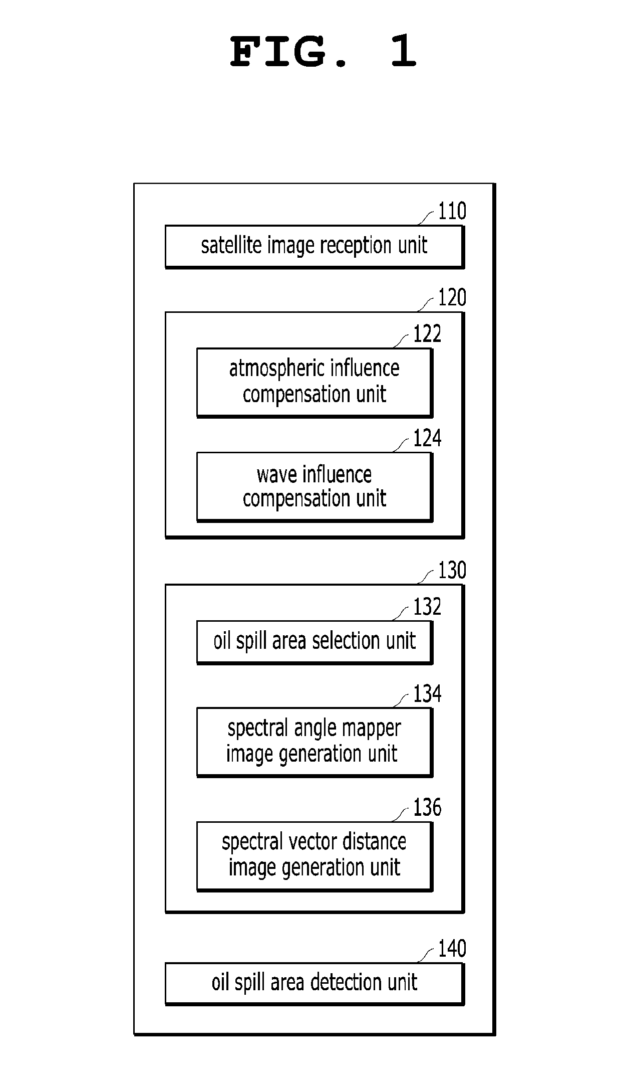
[0034]FIG. 1 is a schematic diagram schematically showing the configuration of an apparatus for detecting an oil spill by using a satellite image according to an embodiment of the present invention.

[0035]Referring to FIG. 1, the apparatus for detecting an oil spill by using a satellite image according to the present embodiment includes: a satellite image reception unit 110 configured to receive a satellite image of a predicted oil spill area in the ocean; a satellite image correction ...


PUM


Abstract

The present invention relates to an apparatus and method for detecting an oil spill by using a satellite image, an apparatus for detecting an oil spill by using a satellite image, the apparatus including: a satellite image reception unit configured to receive a satellite image of a predicted oil spill area; a satellite image correction unit configured to correct the satellite image by compensating for the influences of the atmosphere and waves; a spectral angle mapper image generation unit configured to generate a spectral angle mapper image; a spectral vector distance image generation unit configured to generate a spectral vector distance image; and an oil spill area detection unit configured to derive the range of the oil spill area by combining the spectral angle mapper image and the spectral vector distance image together.

Description

CROSS-REFERENCE TO RELATED APPLICATION[0001]This application is a continuation of PCT / KR2017 / 006506 filed on Jun. 21, 2017, which claims priority to Korean Patent Application No. 10-2016-0082327 filed on Jun. 30, 2016, which application is incorporated herein by reference.TECHNICAL FIELD[0002]The present invention relates to an apparatus and method for detecting an oil spill by using a satellite image, and more particularly to an apparatus and method for detecting an oil spill by using a satellite image, which are capable of improving the reliability of a satellite image of a predicted oil spill area by correcting the satellite image of the predicted oil spill area, and which are also capable of considerably improving accuracy and reliability in the determination of the range of the oil spill area by converting the corrected satellite image into color channel images, generating direction vectors for changes in respective RGB color channels at an arbitrary point of each of the oil sp...

Claims


Application Information

Patent Timeline
Patent Type & Authority Applications(United States)
IPC IPC(8): G06T7/143G01V8/00G01S19/14G06T17/05
CPCG06T7/143G01V8/00G01S19/14G06T17/05G06T2207/10036G06T2207/20056G06T2207/30181G06T2207/20032G06T7/11G06T7/174G06T5/002G06T7/90G06T2207/10032G06T2207/10024
Inventor JUNG, HYUNG SUPPARK, SUNG HWANCHAE, SUNG HO
Owner UNIV OF SEOUL IND COOP FOUND
Why Eureka
Try Eureka