
Vehicular circuit body

Active Publication Date: 2019-05-02
YAZAKI CORP
View PDF5 Cites 11 Cited by
  • Summary
  • Abstract
  • Description
  • Claims
  • Application Information

AI Technical Summary

Benefits of technology

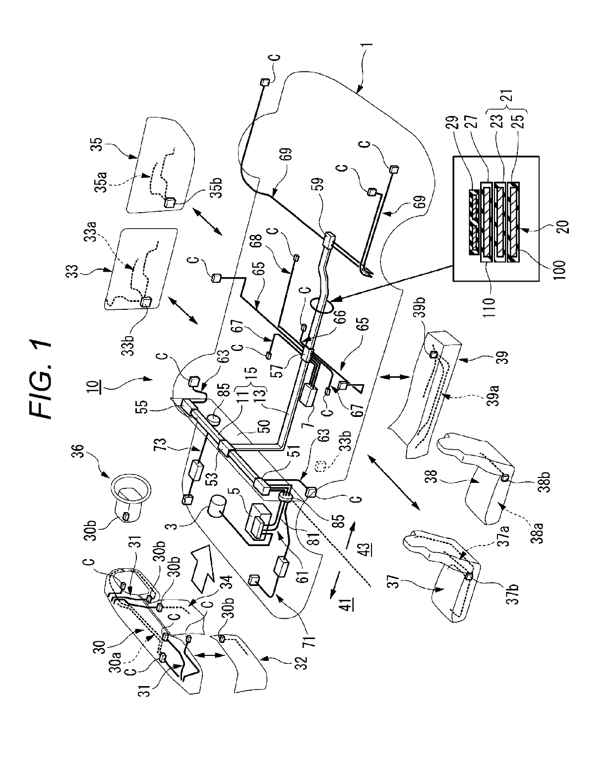
The present invention simplifies the structure of electrical connections between various components and power sources on a vehicle, especially the trunk line portion, to allow for easy addition of new electric wires and miniaturization of the wire harness. This results in a reduction of weight and a more efficient manufacturing process.

Problems solved by technology

In recent years, vehicle systems including such a power source system or communication system have become advanced due to an increase in the number of mounted electric components, complexity of control, or the like.
Along with this, a structure of a wire harness routed on a vehicle body tends to be complicated.
Since a diameter of each electric wire forming the wire harness or the number of electric wires increases due to an increase in the number of electric components mounted on a vehicle, there is a tendency that a size of the entire wire harness increases or a weight thereof increases.
The types and the number of components of wire harness to be manufactured increase due to a difference between vehicle models mounted with a wire harness or increases in types of optional electric components mounted on a vehicle, and thus it is difficult to standardize components forming the wire harness, and component cost or manufacturing cost increases.
In a work process of manufacturing a wire harness, in order to finish the wire harness in a predetermined routing shape, a bundle of a plurality of electric wires forming the wire harness is pulled around over a long distance along a path which is designated in advance, and thus a lot of work time is required.
Since almost all of electric wires are collected at a trunk line portion of the wire harness, the number of bundled electric wires increases, and thus a weight thereof increases.

Method used


Image

  • Vehicular circuit body
  • Vehicular circuit body
  • Vehicular circuit body

Examples


modification examples

[0159]Hereinafter, a detailed description will be made on a modification example of each configuration of the vehicular circuit body 10 according to the first embodiment.

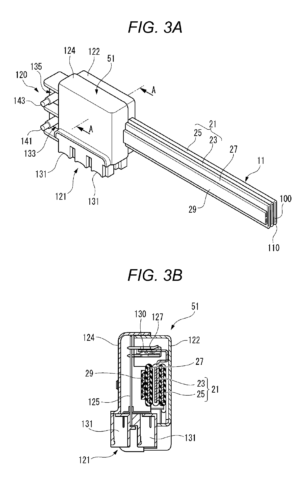
[0160]FIG. 10 is an exploded perspective view illustrating a modification example of a routing material according to the present embodiment.

[0161]A routing material 180 forming a backbone trunk line portion is provided with a power source line 181 and an earth line 183 formed of aluminum flat conductors, and a communication line 185 formed of a flexible printed circuit (FPC).

[0162]Therefore, the routing material 180 can be routed in a state in which the power source line 181 and the earth line 183 are disposed to be adjacent to each other in parallel, and can prevent sneaking of power source noise since the earth line 183 is stacked between the communication line 185 and the power source line 181.

[0163]Since the power source line 181 and the earth line 183 in the routing material 180 are formed of the aluminum flat ...


PUM


Abstract

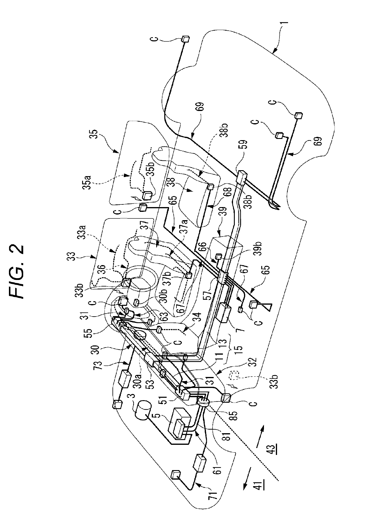
A vehicular circuit body includes: a trunk line that includes a power source line having a predetermined current capacity and a communication line having a predetermined communication capacity, and that is routed in a vehicle body; a branch line that is connected to an accessory; and a plurality of control boxes that are disposed in a distribution manner along the trunk line, each having a control unit that distributes at least one of power from the power source line, supplied to the trunk line, and a signal from the communication line, to the branch line connected to the trunk line. The trunk line is formed of a routing material having at least one kind of conductor among a flat conductor, a round bar conductor, and a stranded wire.

Description

CROSS-REFERENCE TO RELATED APPLICATIONS[0001]This is a continuation of International Application No. PCT / JP2017 / 023312 filed on Jun. 23, 2017, and claims priority from Japanese Patent Applications No. 2016-125287 filed on Jun. 24, 2016, No. 2016-125896 filed on Jun. 24, 2016, and No. 2016-131166 filed on Jun. 30, 2016, the entire contents of which are incorporated herein by reference.TECHNICAL FIELD[0002]The present invention relates to a vehicular circuit body routed in a vehicle.BACKGROUND ART[0003]In a vehicle, for example, source power is required to be appropriately supplied to a large number of various electric components from an alternator (generator) or a battery which is a main power source. A system used to supply such source power is also required to have a function of switching between ON and OFF of the supply of power as necessary, or a function of cutting off a current for each system in a case where an excessive current flows through an electric component.[0004]In a g...

Claims


Application Information

Patent Timeline
IPC IPC(8): B60R16/02H01R31/06H01B7/00
CPCB60R16/0207H01R31/06H01B7/0045B60R16/0215B60R16/03H01B7/0823
Inventor TAKAMATSU, MASAHIROUEZONO, KOICHIKINOSHITA, KOUSUKESAITO, YASUYUKIOIWA, KAZUYUKIFURUTA, TAKUSASAKI, NORIAKINAGANISHI, YUKINARIOKUDA, SADAHARU
Owner YAZAKI CORP
Learn More