Augmented reality display having liquid crystal variable focus element and roll-to-roll method and apparatus for forming the same
Active Publication Date: 2019-05-02
MAGIC LEAP
View PDF2 Cites 13 Cited by
Summary
Abstract
Description
Claims
Application Information
AI Technical Summary
This helps you quickly interpret patents by identifying the three key elements:
Problems solved by technology
Method used
Benefits of technology
[0007]Details of one or more implementations of the subject matter described in this specification are set forth in the accompanying drawings and the description below. Other features, aspects, and advantag
Problems solved by technology
Because the human visual perception system is complex, it is challenging to produce an AR technology that facilitates a com
Method used
Image
Click on the blue label to locate the original text in one second.
Reading with bidirectional positioning of images and text.
Examples
Embodiment Construction
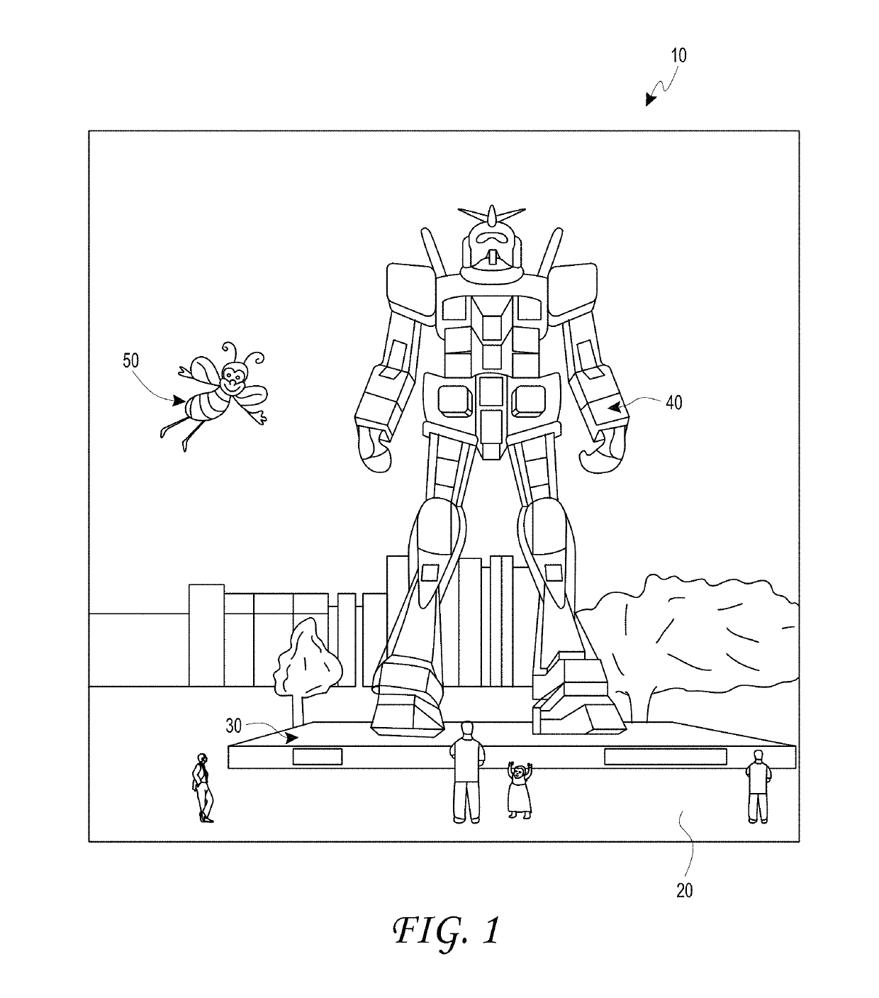
[0065]AR systems may display virtual content to a user, or viewer, while still allowing the user to see the world around them. Preferably, this content is displayed on a head-mounted display, e.g., as part of eyewear, that projects image information to the user's eyes. In addition, the display may also transmit light from the surrounding environment to the user's eyes, to allow a view of that surrounding environment. As used herein, it will be appreciated that a “head-mounted” or “head mountable” display is a display that may be mounted on the head of a viewer or user.
[0066]In some AR systems, a plurality of waveguides may be configured to form virtual images at a plurality of virtual depth planes (also referred to simply a “depth planes” herein). Different waveguides of the plurality of waveguides may have different optical powers, which may provide images that appear to be on different depth planes at different distances from the user's eye. The display systems may also include a ...
PUM
Abstract
A display device includes a waveguide assembly comprising a waveguide configured to outcouple light out of a major surface of the waveguide to form an image in the eyes of a user. An adaptive lens assembly has a major surface facing the output surface and a waveplate lens and a switchable waveplate assembly. The switchable waveplate assembly includes quarter-wave plates on opposing sides of a switchable liquid crystal layer, and electrodes on the quarter-wave plates in the volume between the quarter-wave plates. The electrodes can selectively establish an electric field and may serve as an alignment structure for molecules of the liquid crystal layer. Portions of the adaptive lens assembly may be manufactured by roll-to-roll processing in which a substrate roll is unwound, and alignment layers and liquid crystal layers are formed on the substrate as it moves towards a second roller, to be wound on that second roller.
Description
PRIORITY CLAIM[0001]This application claims the benefit of priority of U.S. Provisional Application No. 62 / 577,678, filed Oct. 26, 2017, entitled “AUGMENTED REALITY DISPLAY HAVING LIQUID CRYSTAL VARIABLE FOCUS ELEMENT AND ROLL-TO-ROLL METHOD AND APPARATUS FOR FORMING THE SAME,” the entirety of which is incorporated herein by reference.INCORPORATION BY REFERENCE[0002]This application incorporates by reference the entirety of each of the following patent applications: U.S. application Ser. No. 14 / 555,585 filed on Nov. 27, 2014, published on Jul. 23, 2015 as U.S. Publication No. 2015 / 0205126; U.S. application Ser. No. 14 / 690,401 filed on Apr. 18, 2015, published on Oct. 22, 2015 as U.S. Publication No. 2015 / 0302652; U.S. application Ser. No. 14 / 212,961 filed on Mar. 14, 2014, now U.S. Pat. No. 9,417,452 issued on Aug. 16, 2016; U.S. application Ser. No. 14 / 331,218 filed on Jul. 14, 2014, published on Oct. 29, 2015 as U.S. Publication No. 2015 / 0309263; U.S. patent application Ser. No. 1...
Claims
Application Information
Patent Timeline
Application Date:The date an application was filed.
Publication Date:The date a patent or application was officially published.
First Publication Date:The earliest publication date of a patent with the same application number.
Issue Date:Publication date of the patent grant document.
PCT Entry Date:The Entry date of PCT National Phase.
Estimated Expiry Date:The statutory expiry date of a patent right according to the Patent Law, and it is the longest term of protection that the patent right can achieve without the termination of the patent right due to other reasons(Term extension factor has been taken into account ).
Invalid Date:Actual expiry date is based on effective date or publication date of legal transaction data of invalid patent.