Input device and method for manufacturing the same

a technology of input device and surface panel, which is applied in the direction of instruments, non-linear optics, other domestic objects, etc., can solve the problems of low productivity, variation in quality among touch panels, and inability to use glass for surface panels, etc., and achieve the effect of low cos

Active Publication Date: 2014-04-17
ALPS ALPINE CO LTD
View PDF0 Cites 3 Cited by
  • Summary
  • Abstract
  • Description
  • Claims
  • Application Information

AI Technical Summary

Benefits of technology

[0014]According to the aspects of the present invention, the decorative layer and the transparent electrode can be formed on planarizing surfaces (i.e., the first surface and the second surface) of the transparent base by roll-to-roll processing. Thus, the input device having high sensor sensitivity can be manufactured with high productivity. Additionally, with a configuration where the transparent panel is bonded to the transparent base with the optical clear adhesive layer interposed therebetween, it is possible to eliminate restrictions on the material of the transparent panel. It is thus possible to realize the input device that can be manufactured with high productivity and has a high degree of freedom for the material of the transparent panel.
[0015]In the input device described above, the first surface may be provided with a transparent protective layer configured to cover a surface of the transparent electrode. This is desirable in that the transparent electrode can be protected.
[0016]In the input device described above, the transparent electrode may have a single-layer structure. This can further reduce the thickness of the input device.
[0018]In the input device described above, a polyethylene terephthalate (pet) film may be used as the transparent base. This makes it possible to manufacture the input device at low cost and to properly apply a roll-to-roll method to the manufacture.

Problems solved by technology

This may lead to lower productivity and cause variations in quality among touch panels.
Moreover, if a roll-to-roll method is adopted in the manufacturing process, it is not possible to use glass for the surface panel in the configuration described in Japanese Unexamined Patent Application Publication No. 2009-301767.
Even if glass is used, there are restrictions on the properties of the glass.

Method used


Image

  • Input device and method for manufacturing the same
  • Input device and method for manufacturing the same
  • Input device and method for manufacturing the same

Examples


Embodiment Construction

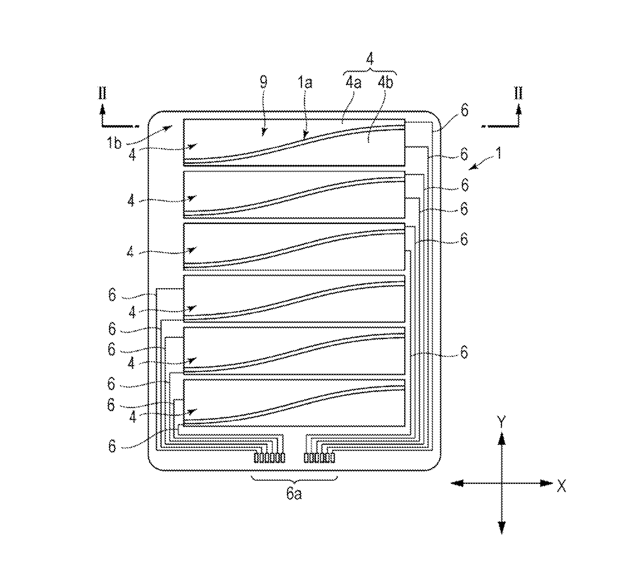
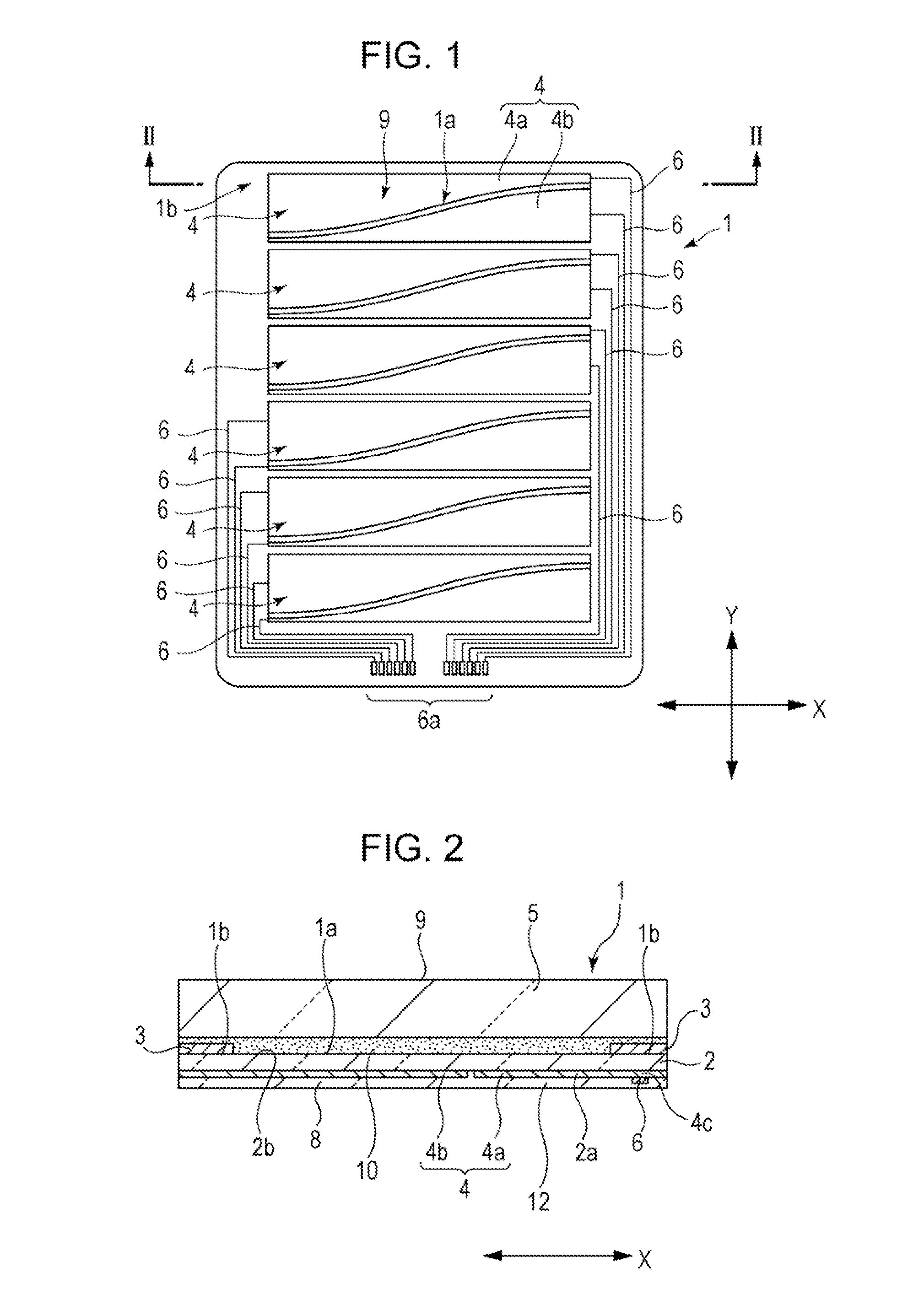
[0026]FIG. 1 is a plan view of a capacitive touch panel (input device) according to an embodiment. FIG. 2 is a vertical sectional view of the touch panel taken along line II-II of FIG. 1 as viewed in the direction of arrows.

[0027]A touch panel 1 includes a flexible transparent base 2, a decorative layer 3, transparent electrodes 4, and a glass panel (transparent panel) 5. The terms “transparent” and “light-transmissive” refer to a state where visible light transmittance is 60% or more (preferably 80% or more). It is more preferable that the haze value is 6 or less.

[0028]For example, a pet film may be preferably used as the flexible transparent base 2. The transparent electrodes 4 are formed on a first surface (lower surface) 2a of the transparent base 2. As illustrated in FIG. 1, the transparent electrodes 4 are formed in a transparent input region 1a of the touch panel 1. The transparent input region 1a extends over a wide range in the center of the touch panel 1. Although the tran...


PUM

PropertyMeasurementUnit
visible light transmittanceaaaaaaaaaa
degree of freedomaaaaaaaaaa

Abstract

An input device is manufactured from a roll of a single-layer flexible transparent base sheet having a first surface and a second surface by forming a transparent electrode pattern and a wiring layer on the first surface. The transparent electrode pattern is disposed in a transparent input region, and the wiring layer extends from an end of the transparent electrode pattern into a decorative region surrounding the transparent input region. A decorative layer pattern is formed on the second surface in the decorative region, while conveying the transparent base sheet through a roll-to-roll processing. The transparent base sheet having the transparent electrode pattern and the decorative layer pattern is divided into individual units. A transparent panel having an operation surface is bonded to the second surface of each of the individual units with an optically clear adhesive layer interposed therebetween.

Description

CLAIM OF PRIORITY[0001]This application is a Divisional of U.S. patent application Ser. No. 13 / 401,749 filed on Feb. 21, 2012 which claims benefit of Japanese Patent Application No. 2011-072493 filed on Mar. 29, 2011, the entire contents of each of which are hereby incorporated by reference.BACKGROUND OF THE INVENTION[0002]1. Field of the Invention[0003]The present invention relates to an input device (touch panel) used in conjunction with a liquid crystal display (LCD) and the like, and to a method for manufacturing the input device.[0004]2. Description of the Related Art[0005]For example, as described in Japanese Unexamined Patent Application Publication No. 2009-301767, a touch panel includes a transparent surface panel (transparent substrate 23), a decorative layer (light-shielding layer 24) formed in a decorative region under the surface panel, a transparent planarizing layer (overcoat layer 25) formed over the entire undersurface of the surface panel and decorative layer, and ...

Claims


Application Information

Patent Timeline
Patent Type & Authority Applications(United States)
IPC IPC(8): B32B17/06
CPCB32B17/064G06F2203/04103Y10T156/1075Y10T156/1052G06F3/0443B32B17/10B29C65/48G02F1/13338B32B2457/208B32B27/36B32B7/12G02B1/14B32B2307/202B32B2307/412B32B2367/00G06F3/041G06F3/0445
Inventor SAITO, SHOJIKOBAYASHI, KIYOSHI
Owner ALPS ALPINE CO LTD
Why Eureka
Try Eureka