Method for producing metal-clad laminate, and metal-clad laminate

a metal-clad laminate and metal-clad technology, applied in the direction of metal layered products, data processing applications, thermoplastic polymer dielectrics, etc., can solve the problems of insufficient solution and insufficient adhesion strength of metal sheets and thermoplastic liquid crystal polymer films, and achieve excellent adhesion strength and inhibit blister generation. , the effect of high frequency characteristics

Active Publication Date: 2019-01-03
KURARAY CO LTD
View PDF39 Cites 2 Cited by
  • Summary
  • Abstract
  • Description
  • Claims
  • Application Information

AI Technical Summary

Benefits of technology

[0039]According to the present invention, it is possible to provide the metal-clad laminate having high frequency characteristics, being excellent in adhesion strength, and inhibiting blister generation. Further, such a metal-clad laminate can be produced in an efficient way.

Problems solved by technology

However, if the metal sheet with low roughness is used from the viewpoint of reducing resistance due to skin effect to make insertion loss small, adhesion strength of metal sheet and thermoplastic liquid crystal polymer film becomes insufficient.
In order to satisfy both small insertion loss and improved adhesion strength, various trials have been made, but still sufficient solution has not been obtained yet.

Method used


Image

  • Method for producing metal-clad laminate, and metal-clad laminate
  • Method for producing metal-clad laminate, and metal-clad laminate
  • Method for producing metal-clad laminate, and metal-clad laminate

Examples


reference example 1

[0125](1) A thermotropic liquid polyester of 27 mol % 6-hydroxy-2-naphthoic acid unit and 73 mol % p-hydroxybenzoic acid unit was melted and kneaded at 280 to 300° C. using a single axis extruder, and extruded from an inflation die with 40 mm in diameter and a slit interval of 0.6 mm to obtain a thermoplastic liquid crystal polymer film 2 with 50 μm in thickness. The melting point Tm and the heat deformation temperature Tdef of this film were 282° C. and 230° C., respectively.

example 1

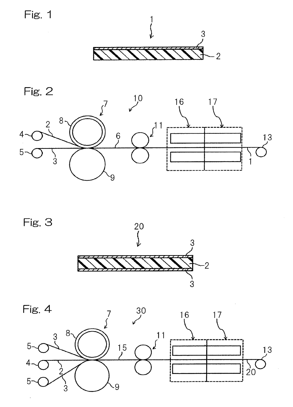
[0126]The thermoplastic liquid crystal polymer film 2 obtained in Reference Example 1 and electrolytic copper foil (ten-point average roughness (Rz): 0.9 μm) with 12 μm in thickness as the metal sheet 3 were used. As shown in FIG. 2, a resin-coated metal roll (“SUPER TENPEX” produced by YURI ROLL MACHINE, CO., LTD., with resin thickness of 1.7 cm) was used as the roll 8 in contact with the thermoplastic liquid crystal polymer film 2. The thermoplastic liquid crystal polymer film 2 was arranged on the side of the resin-coated metal roll 8, and the electrolytic copper foil was arranged on the opposite side thereof. Both of the diameters of the metal roll 9 and the resin-coated metal roll 8 were 40 cm. The surface temperature of the metal roll 9 was set to a temperature 20° C. lower than the melting point of the thermoplastic liquid crystal polymer film 2. The pressure applied to the thermoplastic liquid crystal polymer film 2 and the electrolytic copper foil 3 between rolls was 120 kg...


PUM

PropertyMeasurementUnit
average roughnessaaaaaaaaaa
temperatureaaaaaaaaaa

Abstract

Provided is a method for producing a metal-clad laminate of a thermoplastic liquid crystal polymer film (TLCP film) and a metal sheet(s) bonded to at least one surface of the film using roll-to-roll processing. The metal sheet has a surface with a ten-point average roughness (Rz) of 5.0 μm or less to be bonded to the TLCP film. The method includes preparing the laminate, dry-treating the laminate by subjecting the laminate passed through a dry zone satisfying the following conditions (1) and (2):
    • (1) a drying temperature of lower than the melting point of the TLCP film,
    • (2) for a drying period of 10 seconds or longer, and
    • heat-treating the dried laminate by subjecting the laminate passed through a heating zone on a temperature condition of not lower than the melting point of the TLCP film successively after the dry treatment.

Description

CROSS REFERENCE TO THE RELATED APPLICATION[0001]This application is a continuation application, under 35 U.S.C § 111(a) of international application No. PCT / JP2017 / 008678, filed Mar. 6, 2017, which claims priority to Japanese patent application No. 2016-044549, filed Mar. 8, 2016, the entire disclosure of which is herein incorporated by reference as a part of this application.FIELD OF THE INVENTION[0002]The present invention relates to a method for producing a metal-clad laminate comprising a film of thermoplastic liquid crystal polymer capable of forming an optically anisotropic melt phase (hereinafter, the film and the polymer may be referred to as thermoplastic liquid crystal polymer film and thermoplastic liquid crystal polymer, respectively).BACKGROUND ART[0003]Conventionally, since metal-clad laminates comprising thermoplastic liquid crystal polymer films are excellent in low hygroscopicity, heat resistance, chemical resistance, and electric properties as well as excellent dim...

Claims


Application Information

Patent Timeline
Patent Type & Authority Applications(United States)
IPC IPC(8): B32B15/09B32B37/10B32B15/20H05K3/02C08G63/06C08J5/18
CPCB32B15/09B32B37/10B32B15/20H05K3/022C08G63/065C08J5/18B32B2457/08H05K2201/0129H05K2201/0141H05K2203/0143H05K1/0326H05K1/0346H05K2203/068C08J2367/04B32B15/08B32B37/203B32B37/003B32B37/06B32B37/0053B32B38/0036H05K1/03H05K1/0313H05K3/381H05K3/38H05K3/382B29C66/742B29C65/02B29C66/71B32B2038/0048B32B2307/732B32B2307/514B32B2307/538B32B2305/55H05K2201/0355B32B2457/00G06Q50/10
Inventor NAKASHIMA, TAKAHIROTAKAHASHI, TAKESHIONODERA, MINORU
Owner KURARAY CO LTD
Why Eureka
Try Eureka