X-ray source with ionisation tool

a technology of ionisation tool and x-ray source, which is applied in the direction of x-ray tube vessel/container, x-ray tube gas filling, etc., can solve the problems of reducing the efficiency of the cathode, and reducing the useful life of the cathode, so as to achieve less maintenance and increase the useful life

Active Publication Date: 2019-05-02
EXCILLUM
View PDF29 Cites 20 Cited by
  • Summary
  • Abstract
  • Description
  • Claims
  • Application Information

AI Technical Summary

Benefits of technology

[0005]It is an object of the present invention to provide an X-ray source addressing at least some of the above shortcomings. A particular object is to provide an X-ray source requiring less maintenance and having an increased useful life.

Problems solved by technology

This causes a gradual degradation of the performance of the system, as depositing debris may obscure the window and reduce the efficiency of the cathode.
The charged particles may be particularly detrimental to the cathode as positive ions may be accelerated towards the cathode and cause sputtering damage and corrosion.
Neutral contaminants, such as e.g. vapour, may condense on the cathode and form droplets or larger deposits that degrade the cathode over time.
This degradation process may however be significantly slower than the degradation caused by the charged particles.
The charged and the neutral contaminants may also be detrimental to the X-ray window, on which they may deposit and thereby absorb X-rays, thus reducing the efficiency of the window.
Conversely, because the electrons in the first electron beam typically travel much faster than the charged particles, it will be a more delicate task to design a magnetic field which efficiently prevents debris transport towards e.g. the cathode region or the X-ray window but does still not disturb the first electron beam to a significant level.
However, a larger energy may result in electrons penetrating deeper into the target material and thus a larger fraction of the generated X-ray photons is absorbed by target material before they can be emitted.
Droplets or condense tends to increase local E-field strength which can induce field emission and arcing and thus detoriate and prematurely stress and age high voltage equipment (generator, cabling, etc).

Method used


Image

  • X-ray source with ionisation tool
  • X-ray source with ionisation tool
  • X-ray source with ionisation tool

Examples


Embodiment Construction

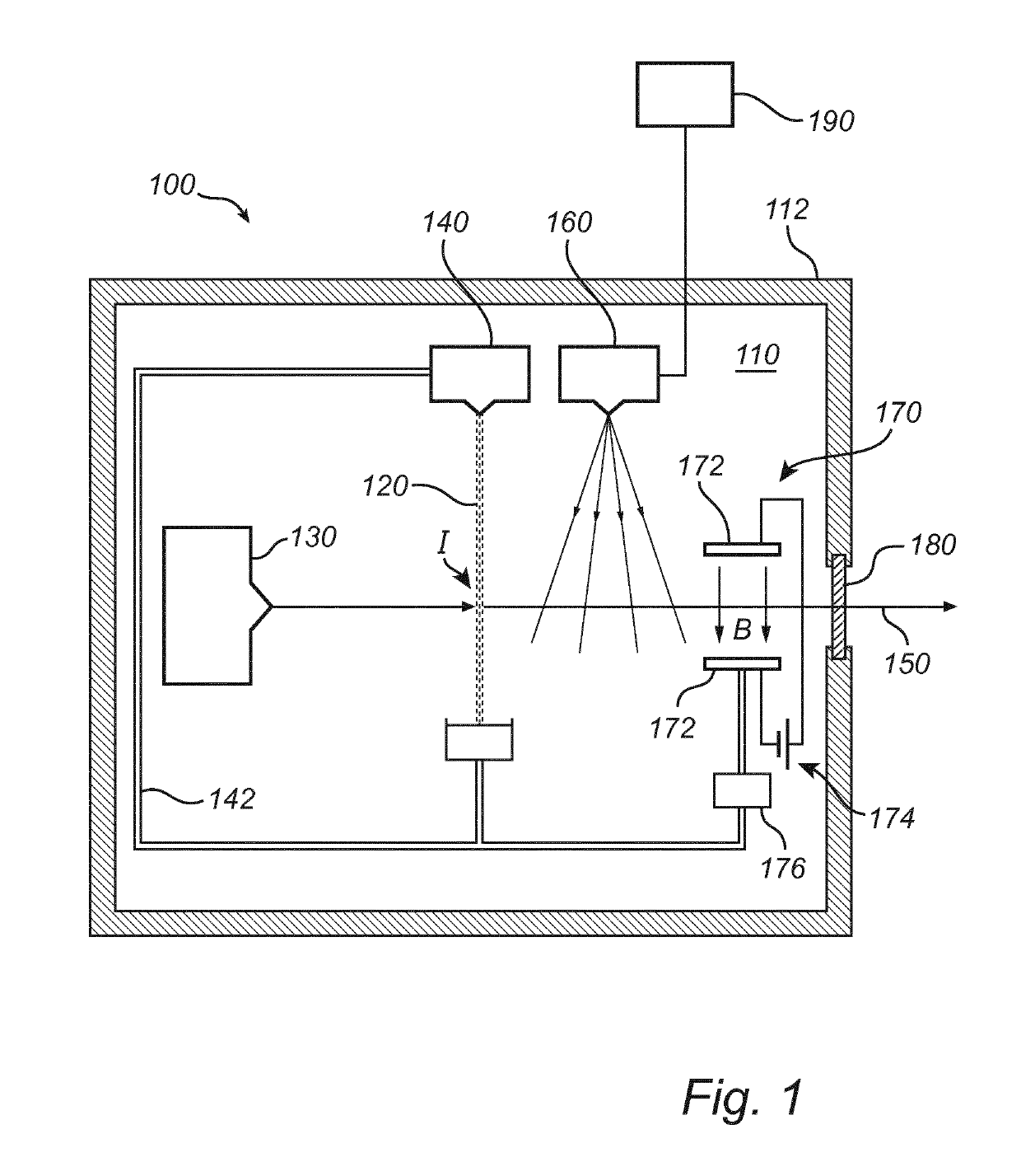
[0047]An X-ray source 100 according to an embodiment of the invention will now be described with reference to FIG. 1. As indicated in FIG. 1, a vacuum chamber 110 may be defined by an enclosure 112 and an X-ray transparent window 180 that separates the vacuum chamber 110 from the ambient atmosphere. The X-rays 150 may be generated from an interaction region I, in which electrons from a first electron beam may interact with a target 120.

[0048]The electron beam may be generated by a first electron source 130, such as an electron gun 130 comprising a high-voltage cathode, directed towards the interaction region I.

[0049]According to the present embodiment, the target 120 may e.g. be formed of a liquid jet 120 intersecting the interaction region I. The liquid jet 120 may be generated by a target generator 140 comprising a nozzle through which e.g. a gas or a liquid, such as e.g. liquid metal may be expelled to form the jet 120 propagating towards and through the interaction region I.

[005...


PUM


Abstract

An X-ray source and a corresponding method for generating X-ray radiation are disclosed. The X-ray source includes a chamber comprising an interaction region, and a first electron source operable to emit a first electron beam, including electrons of a first energy, towards the interaction region such that the first electron beam interacts with a target to generate X-ray radiation. The X-ray source further includes a second electron source adapted to be independently operated to emit a second electron beam including electrons of a second energy for ionising particles in the chamber, and an ion collection tool that is adapted to remove the ionised particles from the chamber by means of an electromagnetic field. By ionising particles and preventing them from moving freely in the chamber, problems related to contamination of the chamber may be mitigated.

Description

TECHNICAL FIELD[0001]The invention disclosed herein generally relates to generation of X-ray radiation. In particular, it relates to an electron-impact X-ray source with an ionisation tool for ionising particles, and an ion collection tool for removing said ionised particles.TECHNICAL BACKGROUND[0002]Systems for generating X-rays by irradiating a liquid target are described in applicant's international applications PCT / EP2012 / 061352 and PCT / EP2009 / 000481, wherein an electron gun comprising a high-voltage cathode is utilised to produce an electron beam that impinges on a liquid jet. The position in space wherein a portion of the liquid jet is hit by the electron beam during operation is referred to as the interaction region or interaction point. The X-ray radiation generated by the interaction between the electron beam and the liquid jet may leave the vacuum chamber through an X-ray window separating the vacuum chamber from the ambient atmosphere.[0003]Free particles, including debri...

Claims


Application Information

Patent Timeline
Patent Type & Authority Applications(United States)
IPC IPC(8): H01J35/20H01J35/18
CPCH01J35/20H01J35/18H01J2235/082H01J2235/168H01J2235/205
Inventor TUOHIMAA, TOMI
Owner EXCILLUM
Why Eureka
Try Eureka