Receiver for high spectral efficiency data communications system using encoded sinusoidal waveforms

Active Publication Date: 2019-05-09
TERAWAVE LLC
View PDF6 Cites 7 Cited by
  • Summary
  • Abstract
  • Description
  • Claims
  • Application Information

AI Technical Summary

Benefits of technology

The patent text describes a system that can transmit a lot of data over a channel by using a modulated sinusoidal waveform. This system is highly efficient in using different parts of the spectrum to transmit data.

Problems solved by technology

An enormous amount of data is being sent using cellular communication systems.
Some problems encountered when transmitting a signal over a transmission channel include transmission path delay, interference, and non-linearity.
Some disadvantages associated with the use of an amplitude modulation signal are that an amplitude modulation signal is not efficient in terms of its power usage, it is not efficient in terms of its use of bandwidth, it requires a bandwidth equal to twice that of the highest audio frequency, and it is prone to high levels of noise.
Although Frequency Modulation has some advantages over Amplitude Modulation some disadvantages include that it requires a more complicated demodulator and that is has a poorer spectral efficiency than some other modulation techniques.
One of the disadvantages of the use of QAM is that for the higher data rates the peak to average power ratio is high.
With conventional QPSK, there is the problem that the transition between two diagonal transmission symbol points in the complex plane passes through the zero point.
On the receiver side, it complicates the necessary synchronization and favors nonlinearities in the transmission path, signal distortion, and unwanted intermodulation.

Method used


Image

  • Receiver for high spectral efficiency data communications system using encoded sinusoidal waveforms
  • Receiver for high spectral efficiency data communications system using encoded sinusoidal waveforms
  • Receiver for high spectral efficiency data communications system using encoded sinusoidal waveforms

Examples


Embodiment Construction

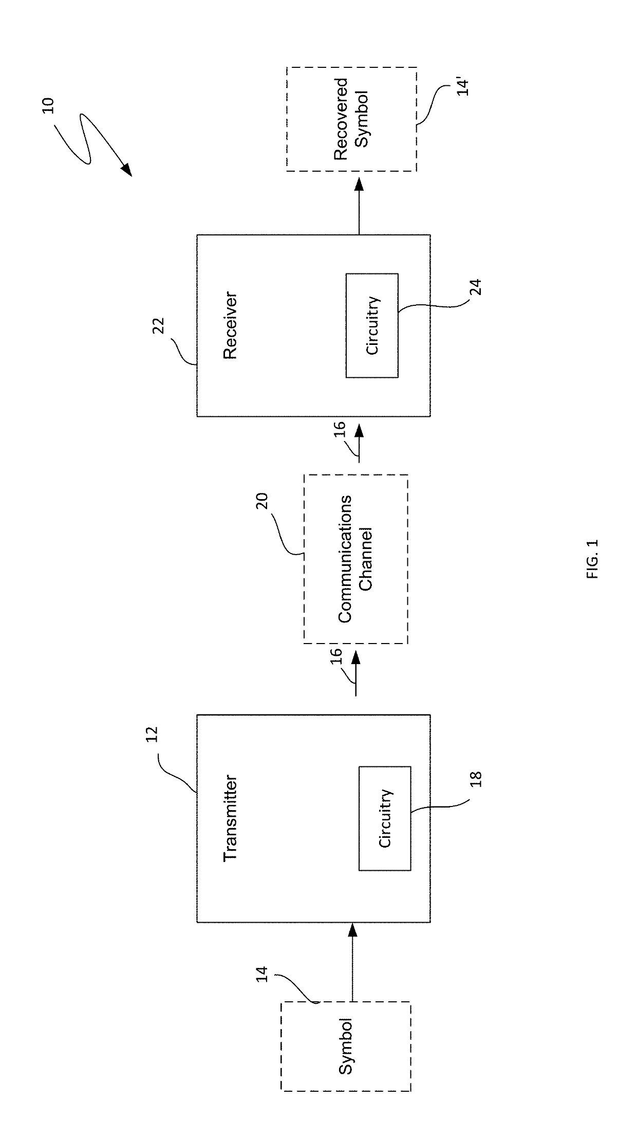
[0065]Referring now to the drawings, wherein like numbers refer to like items, number 10 identifies a communications system constructed according to the present disclosure. With reference now to FIG. 1, the data transmission or communications system 10 is shown to comprise a transmitter 12 for receiving a symbol 14 and for generating a modulated sinusoidal waveform 16 representative of the symbol 14, and circuitry 18 for transmitting the modulated sinusoidal waveform 16 over a communications channel 20. The system 10 also comprises a receiver 22 for receiving the modulated sinusoidal waveform 16, and circuitry 24 for converting the modulated sinusoidal waveform into the symbol 14. The communications channel 20 may be provided by media such as coaxial cable, fiber optic cable, telephone or telephone company (telco) lines such as copper wires, open air as by radio frequency or space or satellite. The channel 20 may carry one or many messages. The system 10 will have input data, such a...


PUM


Abstract

A method of recovering information encoded by a modulated sinusoidal waveform having first, second, third and fourth data notches at respective phase angles, where a power of the modulated sinusoidal waveform is reduced relative to a power of an unmodulated sinusoidal waveform within selected ones of the first, second, third and fourth data notches so as to encode input digital data. The method includes receiving the modulated sinusoidal waveform and generating digital values representing the modulated sinusoidal waveform. A digital representation of the unmodulated sinusoidal waveform is subtracted from the digital values in order to generate a received digital data sequence, which includes digital data notch values representative of the amplitude of the modulated sinusoidal waveform within the first, second, third and fourth data notches. The input digital data is then estimated based upon the digital data notch values.

Description

CROSS-REFERENCE TO RELATED APPLICATIONS[0001]This application claims the benefit of priority under 35 U.S.C. § 119(e) of U.S. Provisional Patent Application No. 62 / 578,332, entitled DATA COMMUNICATIONS SYSTEM WITH HIGH SPECTRAL EFFICIENCY, filed on Oct. 27, 2017, and of U.S. Provisional Patent Application No. 62 / 689,764, entitled HIGH SPECTRAL EFFICIENCY DATA COMMUNICATIONS SYSTEM USING PERIODIC WAVEFORM MODULATION, filed on Jun. 25, 2018, the content of each of which is incorporated herein by reference in its entirety for all purposes.FIELD[0002]The present disclosure pertains generally to data communication systems and, in particular, methods and systems for data communication based upon sine wave modulation.BACKGROUND[0003]There are various transmission channels used for transmitting data or information. Telephone lines consisting of copper wires were used for well over a hundred years for transmitting both voice and data. Radio transmission of radio signals have been around for ...

Claims


Application Information

Patent Timeline
IPC IPC(8): H04L25/49H04L25/06H04L1/00
CPCH04L25/4921H04L25/069H04L1/0045H04L27/389H03K4/92H04L27/3411H04L27/345H04L27/3494H04L27/366H04L27/2017H04L27/2618H04L27/2623H04L27/2627H04L25/03834H04L5/0048H04B1/7176H04B14/06H04L27/04H04L27/26534H04L27/2614H04L27/36
Inventor SCHULTZE, TORSTEN
Owner TERAWAVE LLC
Why Eureka
Try Eureka