

Process monitoring for mobile large scale additive manufacturing using foil-based build materials
- Summary
- Abstract
- Description
- Claims
- Application Information
AI Technical Summary
Benefits of technology
Problems solved by technology
Method used
Image

Examples
first embodiment
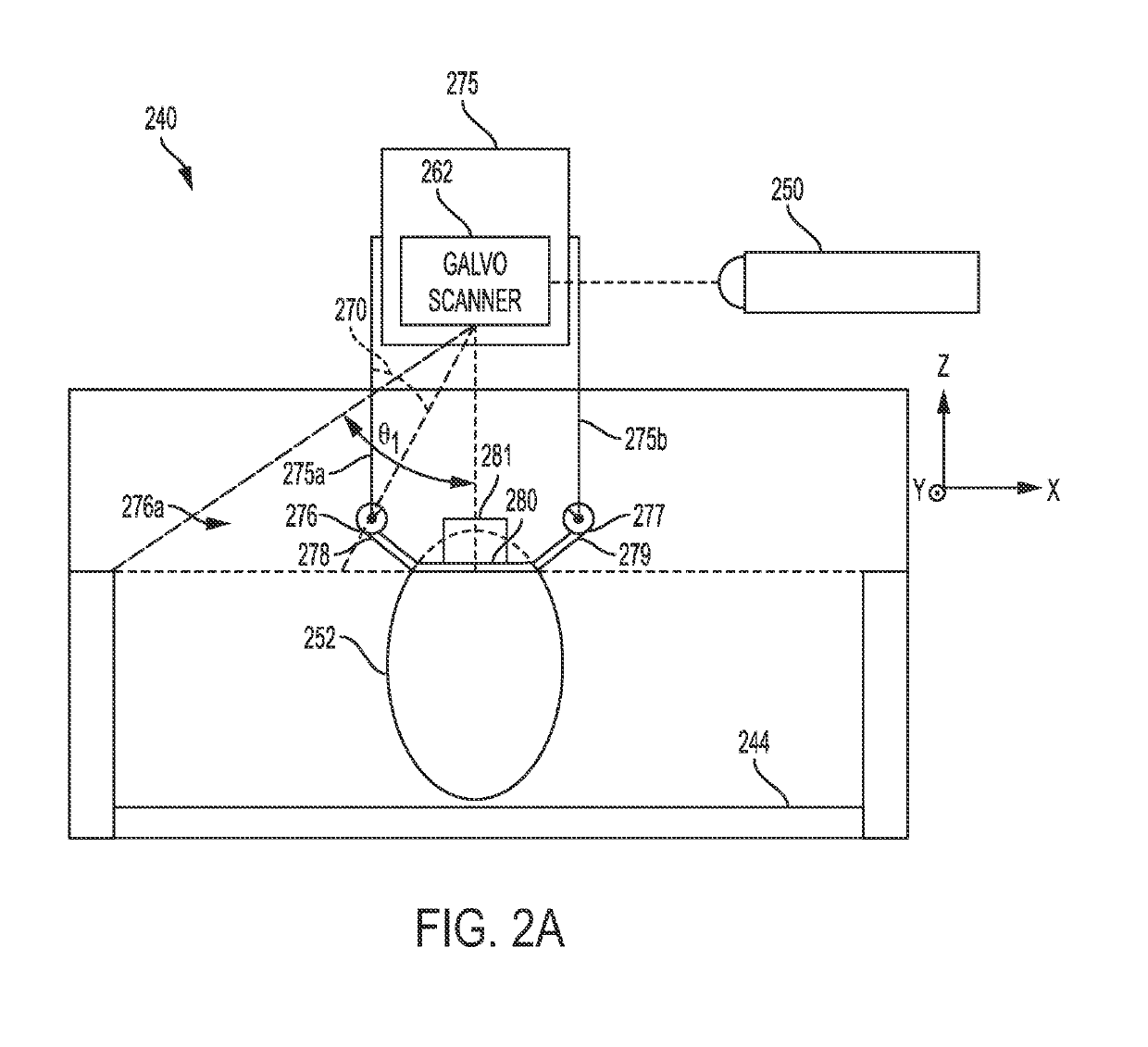
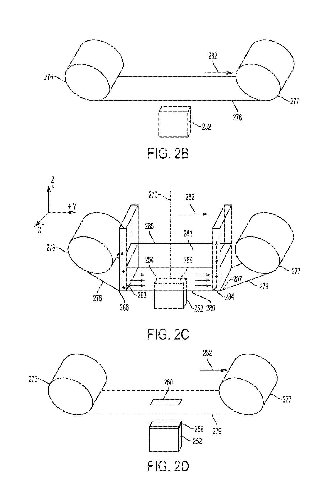
[0047]FIGS. 2A-2D show schematic diagrams of an apparatus 240 according to the present disclosure.
[0048]Apparatus 240 comprises a build plate with a face 244, which is available for building an object by additive manufacturing (FIG. 2A). In some aspects, the build plate and the face 244 lie in an xy-plane, with building occurring in the z-direction relative to face 244. As used herein, the term “above” may mean spaced apart in the z-direction. It should be appreciated that the apparatus 240 may not be confined to a particular gravitational orientation. That is, although the z-direction extends vertically opposite a gravitational direction for the conventional apparatus 100, the apparatus 240 may operate with a z-direction transverse to the gravitational direction, opposite the gravitation direction, or in zero gravity.
[0049]A build unit 275 comprising positioning system 275a, 275b for foil delivery unit 276a, comprising foil supply 276 and foil collector 277, is used to build an obj...
second embodiment
[0069]FIGS. 3A-D show schematic diagrams of an apparatus 340 according to the present disclosure. Apparatus 340 may be similar in some aspects to apparatus 240.
[0070]Apparatus 340 comprises a build plate with a face 344, which is available for building an object by additive manufacturing (FIG. 3A). In some aspects, the build plate and the face 344 lie in an xy-plane, with building occurring in the z-direction relative to face 344. As used herein, the term “above” may mean spaced apart in the z-direction. It should be appreciated that the apparatus 340 may not be confined to a particular gravitational orientation. That is, although the z-direction extends vertically opposite a gravitational direction for the apparatus 100, the apparatus 340 may operate with a z-direction transverse to the to the gravitational direction, opposite to the gravitational direction, or in zero gravity.
[0071]A build unit 375 comprising positioning system 375a, 375b for foil delivery unit 376a, comprising fo...
third embodiment
[0087]FIGS. 4A-4D show schematic diagrams of an apparatus according the present disclosure.
[0088]Apparatus 440 comprises a build plate with two faces 444, 444′, both of which are available for building an object by additive manufacturing (FIG. 4A). In some aspects, the build plate lies in an xy-plane with respect to face 444 and in an x′y′-plane with respect to face 444′, with building occurring in the z-direction relative to face 444 and in the z′-direction relative to face 444′. For simplicity, only building on face 444′ will be discussed, but it is to be understood that the same aspects described for building on face 444′ apply to building on face 444 with equal force.
[0089]As described above, additive manufacturing may be carried out simultaneously on both build plate faces 444, 444′ of apparatus 440. The two faces 444, 444′ are preferably symmetrical. Without wishing to be bound to any particular theory, it is believed that simultaneous, symmetrical additive manufacturing on fa...
PUM
| Property | Measurement | Unit |
|---|---|---|
| Threshold limit | aaaaa | aaaaa |
| Thermal properties | aaaaa | aaaaa |
| Magnetic properties | aaaaa | aaaaa |
Abstract
Description
Claims
Application Information