Collector with return and silt basin, bubbler and process

a collection and silt basin technology, applied in the field of collectors with return and silt basins, bubblers and processes, can solve problems such as ineffectiveness, and achieve the effect of simple, effective and economical

Inactive Publication Date: 2019-05-16
TUCKER RANDALL L
View PDF14 Cites 3 Cited by
  • Summary
  • Abstract
  • Description
  • Claims
  • Application Information

AI Technical Summary

Benefits of technology

[0006]A need also exists to coordinate operation of the system for a large scale collector, e.g., on the order of over 30 feet or greater. Individual, smaller sized collectors can be effectively manufactured, shipped, and subsequently assembled or joined together to address a need for a large scale collector.
[0008]The present invention provides a collector that meets the above-noted needs and others in a simple, effective, and economical manner.
[0011]In another aspect, the collector includes a mechanism or means for controlling suction / intake during the pumping sequence to effectively remove sediment from the cavity.
[0013]For example, one preferred process handles removal of sediment that has migrated into the cavity or hopper of the collector. Both pumps are initially off. At start-up, the first / inject pump is started and operated at an elevated speed (e.g., maximum GPM). The inject pump directs water flow through a first / inject port that communicates with the sediment in the hopper, and the sediment is loosened. Thereafter, the second / suction pump is started and operated at the same speed as the first pump thereby allowing the system to flush a second / suction port with water from the inject pump. Subsequently, the sediment and water exit the hopper through the suction port. The speed of the first pump is reduced which allows the difference of the flow rates of the pumps to be balanced out by suctioning the hopper flow into the suction port and to the discharge. By subsequently increasing the speed of the first pump, sediment suction then decreases from the hopper, and the suction port / line is purged with sediment-free suction water purging the system. Next the suction pump is shut down after being purged and the inject pump speed increased to pump directly into the hopper and make sure the collector is not bridged. Thereafter the inject pump is shut down.

Problems solved by technology

In particular, capturing silt in addition to other sediment would be a substantial improvement and heretofore has not been effectively achieved.

Method used


Image

  • Collector with return and silt basin, bubbler and process
  • Collector with return and silt basin, bubbler and process
  • Collector with return and silt basin, bubbler and process

Examples


Embodiment Construction

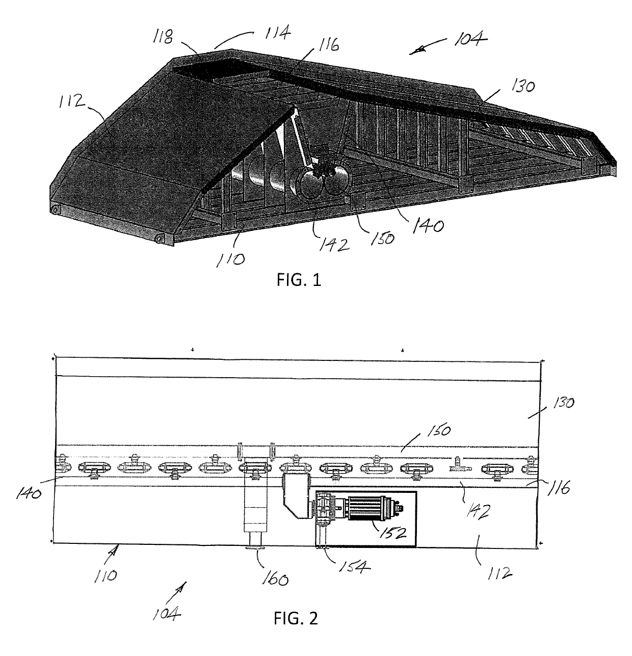
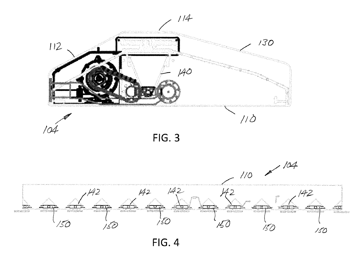
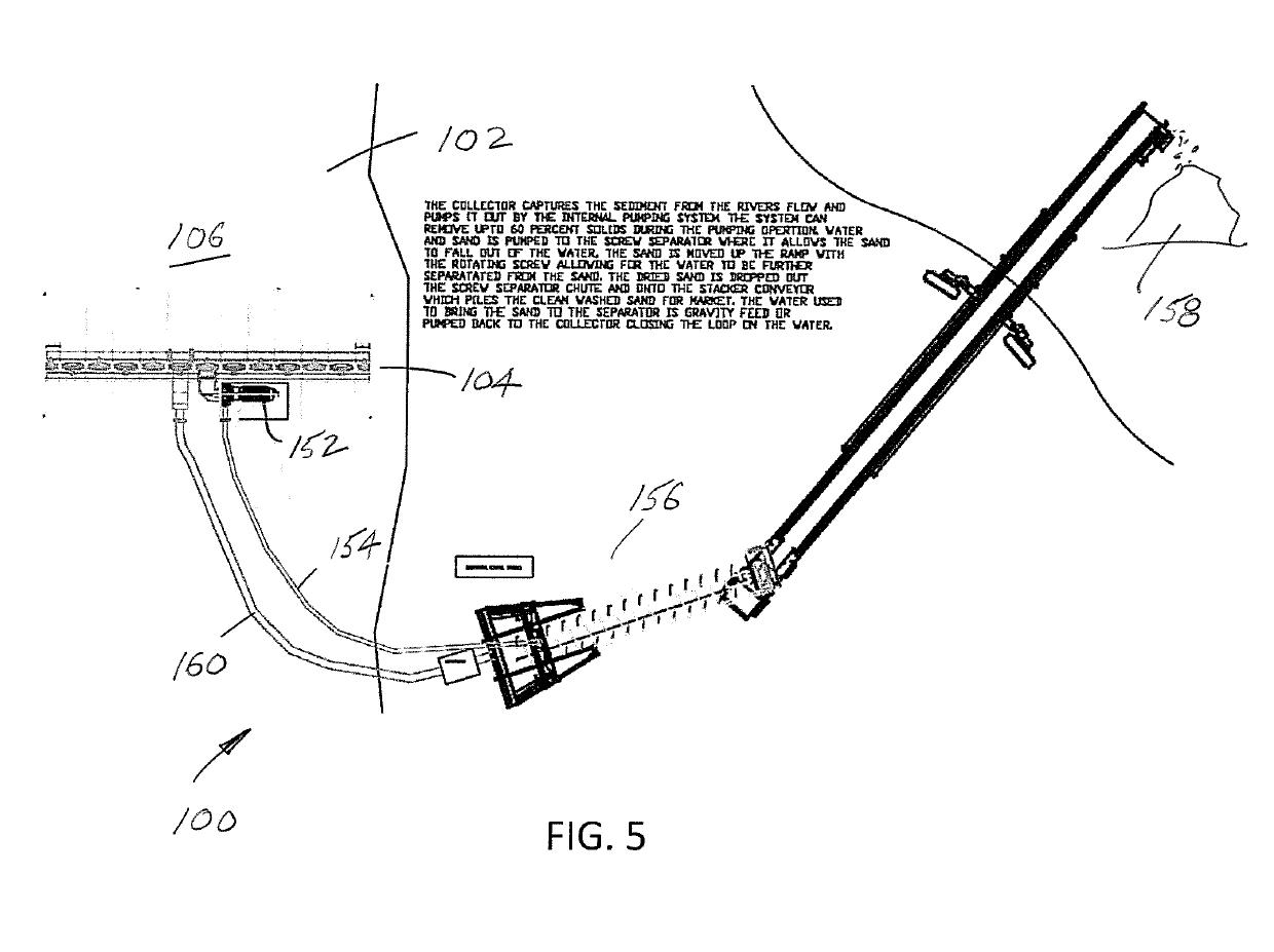
[0033]FIGS. 1-5 illustrate a collector system 100 used in a waterway 102 for selectively removing sediment (sand, gravel, fines, organic material, silt, suspended material, debris, particulates, colloids, heavy metals, and / or contaminants) therefrom. The collector system 100 (that preferably includes one of more collectors 104) is typically located and secured along a base or bottom surface 106 of the waterway 102 or partially embedded in the bottom surface of the waterway and usually oriented in a direction angled or generally perpendicular to the water flow (WF) to extend across the waterway. If multiple collectors 104 are used, the collectors are interconnected via connectors, for example, at each end of the system 100. Thus, it will be appreciated that a series of collectors 104 can be connected together, e.g., daisy-chained, to extend across various widths of the waterway 102 or a portion of the width of the waterway.

[0034]With continued reference to FIG. 1, one type of collect...


PUM

PropertyMeasurementUnit
total weightaaaaaaaaaa
solubleaaaaaaaaaa
speedaaaaaaaaaa

Abstract

A collector includes one or more air / oxygen / gas introduction ports to form a bubbler that produces curtains of air / oxygen / gases into the waterway. The bubbler can be integrated into the collector, or formed as a separate component used with or without the collector. First and second pumps provide for improved removal of sediment collected in the collector cavity.

Description

BACKGROUND[0001]This application claims the priority benefit of U.S. provisional application Ser. No. 62 / 349,065, filed Jun. 12, 2016, the disclosure of which is incorporated herein by reference.[0002]The present disclosure relates to an apparatus, system, device, and method of removing sediment, sand, gravel, fines, organic material, silt, suspended material, debris, and / or particulates (generically referred to as sediment) from a waterway, etc. It is also capable of removing colloids, heavy metals and contaminants that travel near the bottom of the flow. The new collector is designed to cause the particles to fall out of the water column.[0003]U.S. Pat. No. 6,042,733 (and patents claiming priority therefrom) relates to a collector that provides a simple, economical structure effective in filtering and removing sediment from a waterway, such as a river, stream, creek, irrigation channel, tidal pool, estuary pool, ocean, etc. The details of the U.S. Pat. No. 6,042,733 patent are exp...

Claims


Application Information

Patent Timeline
Patent Type & Authority Applications(United States)
IPC IPC(8): C02F7/00C02F1/68B01F3/04B08B9/093
CPCC02F7/00C02F1/688B01F3/04248B08B9/0933B01F2003/04312B01F2003/04319B01F2215/0052C02F2103/007Y02W10/10B01F23/231264B01F23/23121B01F23/231265B01F2101/305
Inventor TUCKER, RANDALL L.
Owner TUCKER RANDALL L
Why Eureka
Try Eureka