
Robot cleaner

Active Publication Date: 2019-05-23
SAMSUNG ELECTRONICS CO LTD
View PDF0 Cites 1 Cited by
  • Summary
  • Abstract
  • Description
  • Claims
  • Application Information

AI Technical Summary

Benefits of technology

The present invention describes a robot cleaner that can improve cleaning efficiency and reduce noise. Additionally, it can prevent the fan motor's suction force from becoming weaker.

Problems solved by technology

However, when the suction force of a fan motor is weak, cleaning efficiency may deteriorate.
At this time, if the robot cleaner makes a loud noise, the user may find it uncomfortable to do the activity.

Method used


Image

  • Robot cleaner
  • Robot cleaner
  • Robot cleaner

Examples


Embodiment Construction

[0043]Hereinafter, a robot cleaner according to an embodiment will be described in detail with reference to the accompanying drawings.

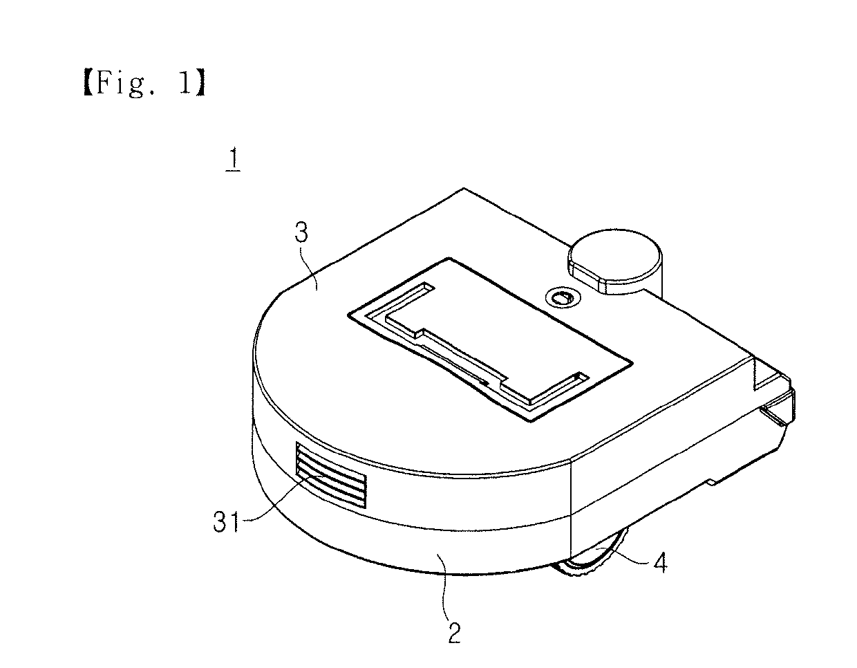
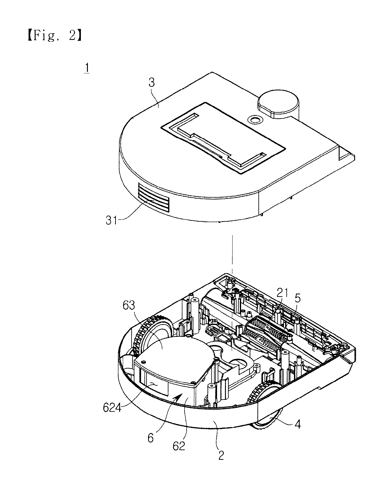
[0044]FIG. 1 is a perspective view of a robot cleaner according to an embodiment, and FIG. 2 is an exploded perspective view of a robot cleaner according to an embodiment.

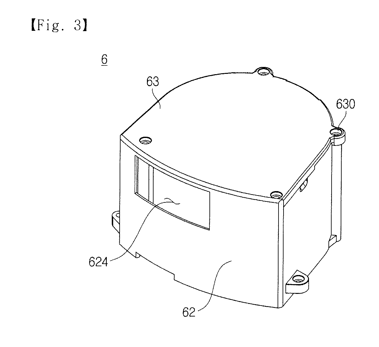
[0045]Referring to FIGS. 1 and 2, a robot cleaner 1 according to an embodiment may include cases 2 and 3 forming an outer appearance, a fan motor unit 6 for generating a suction force, and wheels 4 for driving the robot cleaner 1. Also, a brush unit 5 may be installed at one side of the robot cleaner 1. The brush unit 5 may be rotatably configured to pick up foreign materials on the floor. The robot cleaner 1 may further include a dust collector (not shown) for filtering out foreign materials included in inhaled air to collect the foreign materials.

[0046]The cases 2 and 3 may include a lower case 2 in which the fan motor unit 6, etc. are accommodated, and a upper case 3 covering the ...


PUM


Abstract

By improving a structure of a discharge flow path of a robot cleaner, it may be possible to minimize a loss of a suction force, thereby reducing a noise without deteriorating cleaning efficiency. The robot cleaner includes a fan motor configured to generate a suction force, a first housing in which the fan motor is accommodated, a second housing in which the first housing is accommodated, and a chamber positioned between the first housing and the second housing, wherein a plurality of slits are formed in the chamber.

Description

TECHNICAL FIELD[0001]The present disclosure relates to a robot cleaner capable of reducing a noise.BACKGROUND ART[0002]A robot cleaner is equipment that performs cleaning by autonomously traveling on an area to be cleaned without a user's operation and sucking foreign substances such as dust from the floor. During cleaning, the robot cleaner determines a distance to an obstacle, e.g., furniture, office appliances, walls, etc., present in the cleaning area through a distance sensor, and changes its driving direction based on the determined distance to clean the cleaning area.[0003]The robot cleaner includes a main body with a fan motor and wheels for driving the main body. In the bottom of the main body, a suction portion is provided to suck dust on the floor by a suction force of the fan motor. The sucked dust is collected in a dust collector installed in the inside of the main body. In the suction portion, a brush for picking up foreign substances on the floor is installed. The bru...

Claims


Application Information

Patent Timeline
IPC IPC(8): A47L9/16G10K11/162A47L9/22
CPCA47L9/1658G10K11/162A47L9/22A47L11/4011A47L2201/04A47L9/0081A47L9/1608A47L9/1666A47L9/2842A47L2201/00
Inventor KWON, KI HWANYOON, JIN WOOKKIM, DONG WOOKHA, DONG WOOHONG, SEOK MAN
Owner SAMSUNG ELECTRONICS CO LTD
Learn More