
Auto-tensioner

Active Publication Date: 2019-05-23
NTN CORP
View PDF0 Cites 0 Cited by
  • Summary
  • Abstract
  • Description
  • Claims
  • Application Information

AI Technical Summary

Benefits of technology

The present invention aims to prevent the fixing tool of an auto-tensioner from coming off during use. This is achieved by minimizing the deformation of the engaging pieces on the tapered surfaces of the cylinder and spring seat when the engaging pieces sandwich the spring seat and cylinder from the axially opposite direction. This ensures that the diametrical distances between the engaging pieces on the opposite sides of the cylinder and spring seat increase, thereby preventing the fixing tool from coming off.

Problems solved by technology

One problem with the fixing tool of Patent Document 1 is that it cannot stably and rigidly hold an auto-tensioner as disclosed in Patent Document 2 in the contracted position.
However, such a fixing tool cannot be used if a cutting tool for cutting the fixing tool cannot be used.

Method used


Image

  • Auto-tensioner
  • Auto-tensioner
  • Auto-tensioner

Examples


first embodiment

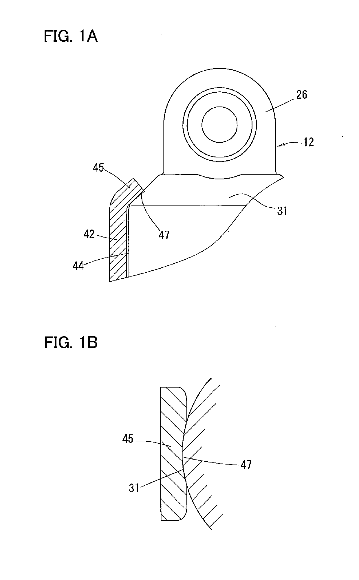
[0074]In the first embodiment, as described above, since the concave surfaces 47 and 48 of the inclined engaging pieces 45 and 46, which are opposed to the tapered surfaces 16 and 31, are configured to contact the tapered surfaces 16 and 31 over circumferentially extending areas (as shown in FIGS. 1A, 1B, 6A and 6B), the wedge effect is weak, so that the diametrical distances between the respective opposed pairs of engaging pieces 45 and 46 do not increase considerably, making the fixing tool 40 less likely to come off the cylinder 9 and the spring seat 12. Also, any force that tends to move the fixing tool 40 in the fore-and-aft direction relative to the cylinder 9 and the spring seat 12 will result in the concave surface 47, 48 of each engaging piece 45, 46 engaging, in the fore-and-aft direction, one of the right and left ends of the portion of the tapered surface 16, 31 that is located inside of the concave surface 47, 48, thus making the fixing tool 40 even less likely to come ...

fourth embodiment

[0078]The auto-tensioner according to the present invention is described with reference to FIGS. 11-14.

[0079]As shown in FIGS. 11, 12A and 12B, the fixing tool 70 of the fourth embodiment differs from that of the third embodiment only in that lower engaging pieces 62 are different in shape from the lower engaging pieces of the third embodiment. In particular, the lower engaging pieces 62 are bent inwardly at front end portions 71 (facing the opening). The front end portions 71 of the respective lower engaging pieces 62 are located forwardly of the respective ends of the diametrical lines of the tapered surface 16 extending in the right-and-left direction, and are bent inwardly.

[0080]FIG. 13 shows a section taken along line XIII-XIII of FIG. 12B, while FIG. 14 shows a section taken along line XIV-XIV of FIG. 12A. As shown in FIGS. 11, 13 and 14, the front end portions 71 of the respective lower engaging pieces 62 are curved so as to extend along the areas of the tapered surface 16 lo...


PUM


Abstract

A fixing tool of an auto-tensioner includes inwardly inclined engaging pieces inclined inwardly so as to be opposed to respective tapered surfaces of a spring seat and a cylinder of the auto-tensioner. The engaging pieces have concave surfaces that contact the tapered surfaces over a circumferentially extending area. This minimizes the deformation of the engaging pieces such that the diametrical distances therebetween increase due to contact with the tapered surfaces when sandwiching the spring seat and the cylinder with the engaging pieces from the axially opposite directions, thereby preventing the fixing tool from coming off.

Description

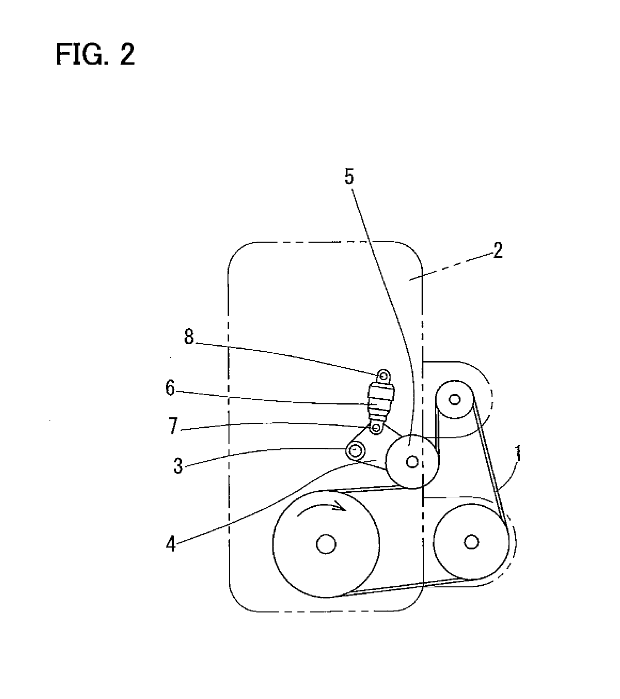
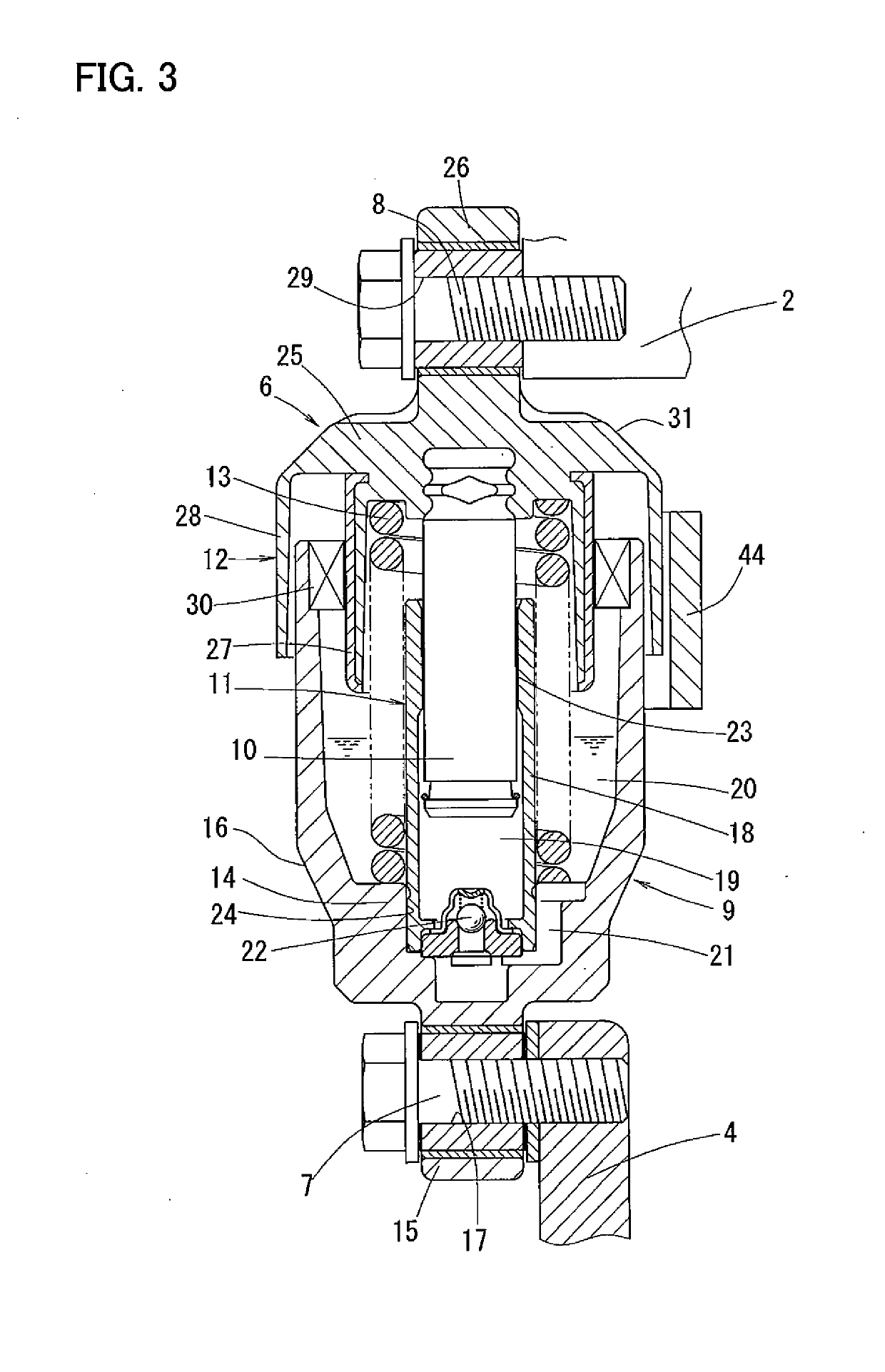
TECHNICAL FIELD[0001]The present invention relates to an auto-tensioner used to maintain the tension of an engine accessory driving belt for driving automotive engine accessories such as an alternator.BACKGROUND ART[0002]Automotive engine accessories, such as an alternator, an air-conditioner, and a water pump, have their respective rotary shafts coupled to an engine crankshaft by an engine accessory driving belt, and are driven by the engine through the engine accessory driving belt. In order to keep the tension of the engine accessory driving belt within an proper range, a tension adjusting device is used which comprises pulley arm pivotable about a support shaft, a tension pulley rotatably mounted on the pulley arm, and an auto-tensioner that biases the pulley arm in a direction in which the tension pulley is pressed against the engine accessory driving belt.[0003]Among conventional auto-tensioners used in such a tension adjusting device, a hydraulic auto-tensioner is known that ...

Claims


Application Information

Patent Timeline
IPC IPC(8): F16H7/12F02B67/06F16H7/08F16B2/24
CPCF16H7/1236F02B67/06F16H7/0836F16H7/0848F16H7/08F16B2/24F16H2007/0812F16H2007/0859F16H2007/0865F16H2007/0893F16H2007/0878F16B2/22F16H7/12
Inventor HONDA, NAOTOTANAKA, TADAHISA
Owner NTN CORP
Learn More