
Robot joint space point-to-point movement trajectory planning method

a robot and trajectory planning technology, applied in the direction of electric programme control, programme-controlled manipulators, programme control, etc., can solve the problems of affecting the efficiency of the robot in actual machining, failing to meet the requirements of real-time control, etc., to reduce the number of trajectory planning, reduce the effect of ensuring the operation efficiency of the robot, and small calculation amoun

Active Publication Date: 2019-05-30
NANJING ESTUN ROBOTICS CO LTD
View PDF0 Cites 11 Cited by
  • Summary
  • Abstract
  • Description
  • Claims
  • Application Information

AI Technical Summary

Benefits of technology

The invention provides a trajectory planning method for point-to-point motion in a robot that allows the robot to smoothly move at an optimal time and improve its motion tempo during an actual working task. The method has a consistent change trend among the motion curves of all axes, which ensures that the robot operates without impact and has low loss, and can maximize its moving capability within a limited range of parameters. The method meets the requirements on real-time performance in robot control and is suitable for field applications of industrial robots.

Problems solved by technology

Robots generally have multiple axes, and a PTP motion using the above method requires multiple trajectory planning with a huge calculation amount such that trajectory points may not be generated in a control cycle during the real-time planning in robot control, thus failing to meet the requirements on real-time control.
Therefore, the motion time selected by the method of the patent is not necessarily an optimal time for the PTP motion, and it may take a longer time to complete a PTP motion, thus affecting the efficiency of the robot in actual machining.

Method used


Image

  • Robot joint space point-to-point movement trajectory planning method
  • Robot joint space point-to-point movement trajectory planning method
  • Robot joint space point-to-point movement trajectory planning method

Examples


Embodiment Construction

[0027]In order to make the objects, technical solutions and advantages of the invention clearer, the invention will be further described below in detail with reference to the drawings and particular embodiments.

[0028]An SCARA robot will be taken as an example to illustrate the specific implementation of the method of the invention.

[0029]An SCARA (Selective Compliance Assembly Robot Arm) is a cylindrical coordinate industrial robot. The SCARA robot comprises 4 axes, 3 of which are rotary axes whose axial lines are parallel to each other for positioning and orientation in a plane, and the other one of which is a moving axis for completing the motion of an end piece perpendicular to the plane.

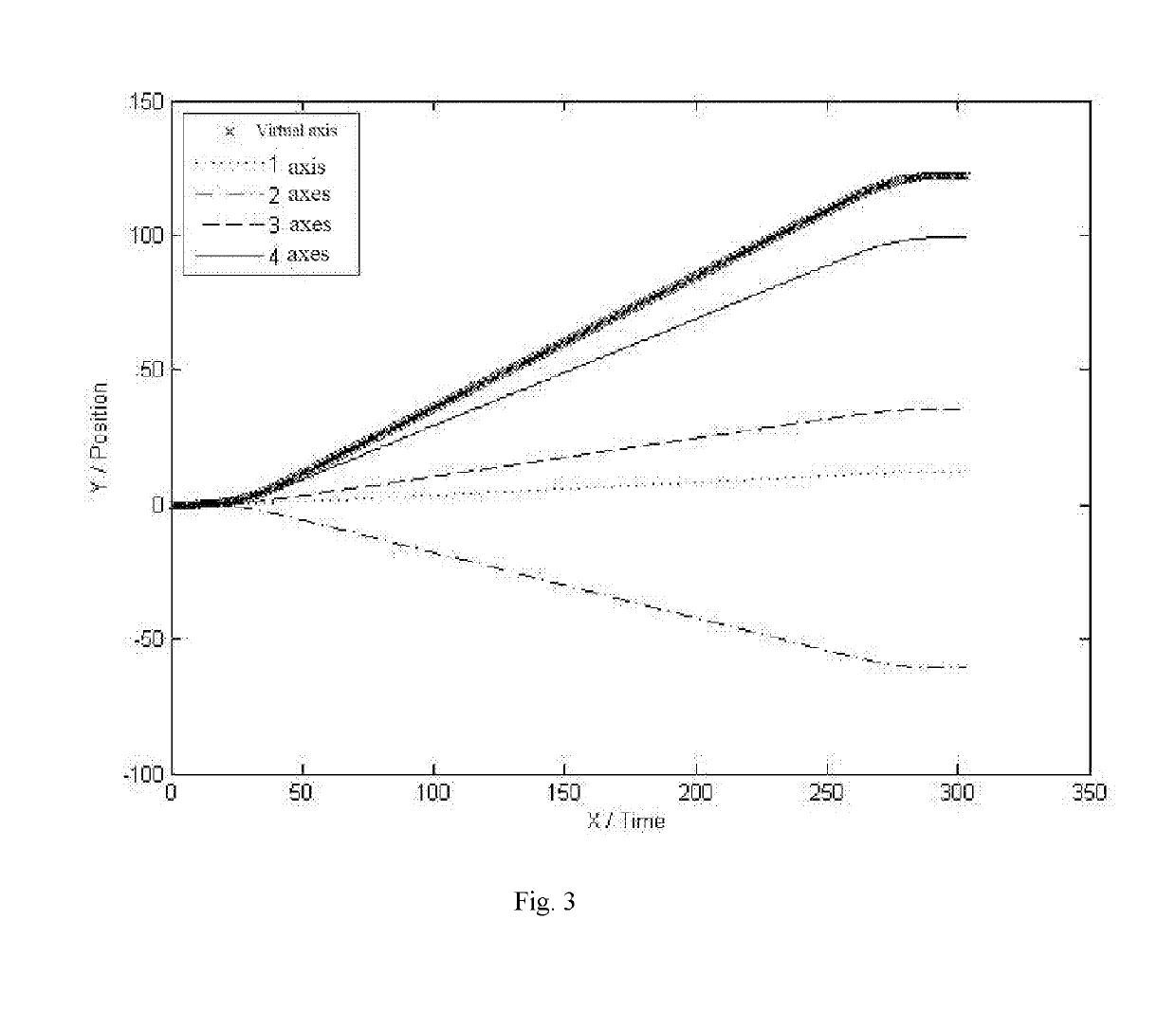
[0030]In the actual working process, the maximum velocity of all the axes of the SCARA robot can be set to 100° / s, 100° / s, 100 mm / s and 100° / s respectively; the maximum acceleration thereof can be set to 1000° / (s*s), 1000° / (s*s), 1000 mm / (s*s) and 1000° / (s*s) respectively; and the maximum jerk the...


PUM


Abstract

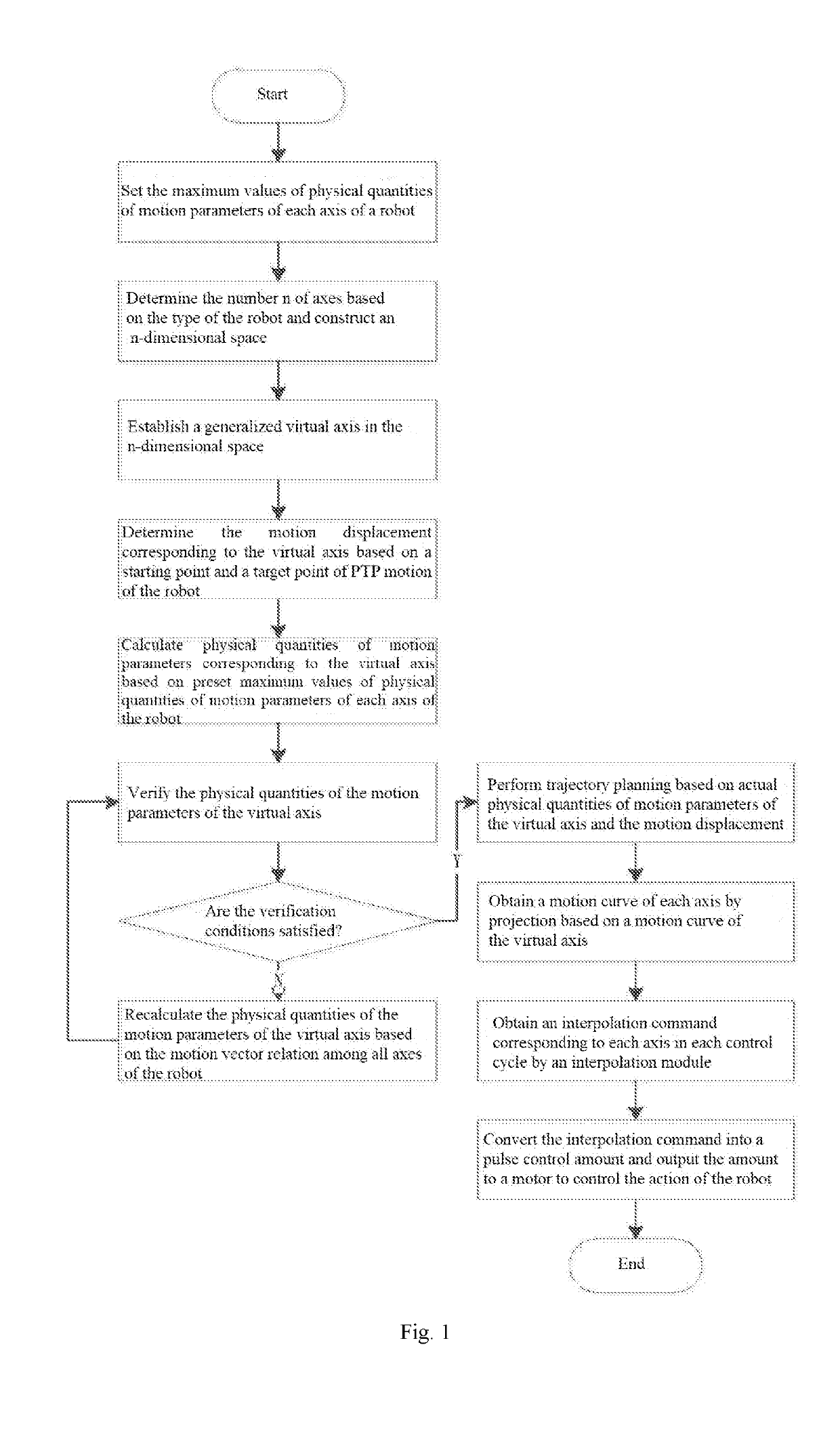
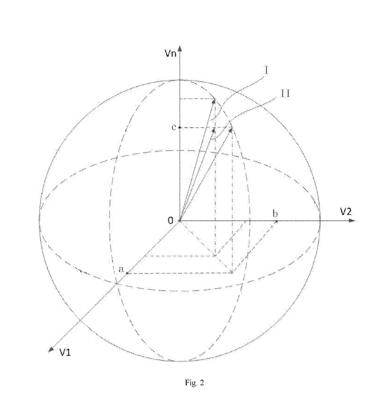
A robot joint space point-to-point movement trajectory planning method. Joint space trajectory planning is performed according to the displacement of a robot from a start point to a target point during PTP movement and a limitation condition of a preset movement parameter physical quantity of each axis in a robot control system. An n-dimensional space is constructed by taking each axis of the robot as a vector, wherein n ≥2, and the movement parameter physical quantity of each axis of the robot is verified according to a vector relationship between the n axes of the robot, so that a trajectory planning curve of each axis of the robot satisfies the limitation condition of the preset movement parameter physical quantity. The method has a small amount of calculations and strong real-time performance, the movement curves are mild, the control time is optimal, and the algorithm execution effect is good.

Description

FIELD OF THE INVENTION[0001]The invention relates to a trajectory planning method for a robot, and particularly to a trajectory planning method for point-to-point motion in robot joint space.BACKGROUND OF THE INVENTION[0002]With the development of modern technology, industrial robots have more and more applications, and the forms of working tasks in various application fields get more diversified as well. There are high requirements on real-time control in a robot application scenario such that a robot control system needs to provide an efficient motion control strategy. As a key technology in a robot control system, the trajectory planning of robot motion directly determines the operating efficiency of the control system and plays an important role in whether a robot can complete high-speed and high-precision machining.[0003]There are two kinds of motion trajectories commonly used by robots: linear and arc motion trajectories in Cartesian space; and point-to-point motion trajectori...

Claims


Application Information

Patent Timeline
Patent Type & Authority Applications(United States)
IPC IPC(8): B25J9/16G05B19/19
CPCB25J9/1664B25J9/1653G05B19/19G05B2219/40519G05B2219/39206
Inventor FENG, RIYUEWANG, JIHUXIA, ZHENGXIANPAN, TINGTINGWU, BOJING, SHUYI
Owner NANJING ESTUN ROBOTICS CO LTD
Learn More