Packing material including cushion

a cushion and packaging technology, applied in the field of cushioning, can solve the problems of increasing the quantity difficulty in downsizing, and difficulty in recycling, and achieve the effects of increasing the number of components, reducing the number of disposed packing materials, and high buffering

Inactive Publication Date: 2019-05-30
KONICA MINOLTA INC
View PDF0 Cites 5 Cited by
  • Summary
  • Abstract
  • Description
  • Claims
  • Application Information

AI Technical Summary

Benefits of technology

[0009]The present disclosure aims at solving the above-described problems, and specifically, at providing packing material enabling cushions to exert sufficiently high resistance against gas moved between the bags by external forces, and to restore their buffering capacity by release from the external forces, without increase in number of their components or complicating their structures.

Problems solved by technology

Increase in quantity of disposed packing materials is considered problematic, following the increase of interest toward environmental problems such as global warming.
Use of foamed plastic, specifically as block-type cushions has problems such as difficulty in downsizing (being voluminous,) difficulty in recycling, and a significant amount of heat emission and generation of various kinds of harmful gases when burned.
However, air cushions are disadvantageous in that their bags easily rupture when receiving an external shock, which requires a measure for further improving their buffering effects.
However, such devices increase the number of components and complicate the structures, and therefore, are disadvantageous in production cost reduction.
However, the gas pressure difference is often too low to surely return all the gas to the original bag.
Accordingly, it is difficult to ensure that the bag having received the external force fully restores its buffering capability after the bag is released from the external force.
If the bag has a smaller amount of gas due to the insufficient restoration, problems caused by lowering of the buffering effect may occur when the bag receives an external force again; for example, the package may be damaged by a collapse of the bag (a phenomenon in which the gas pressure of the bag fails to resist the external force, and consequently, the film on one side of the bag by receiving the external force falls down and collides with the film on the other side.)

Method used


Image

  • Packing material including cushion
  • Packing material including cushion
  • Packing material including cushion

Examples


Embodiment Construction

[0022]Hereinafter, one or more embodiments of the present invention will be described with reference to the drawings. However, the scope of the invention is not limited to the disclosed embodiments.

[0023]The following describes an embodiment of the present disclosure, with reference to the drawings.

[Appearance of Image Forming Device]

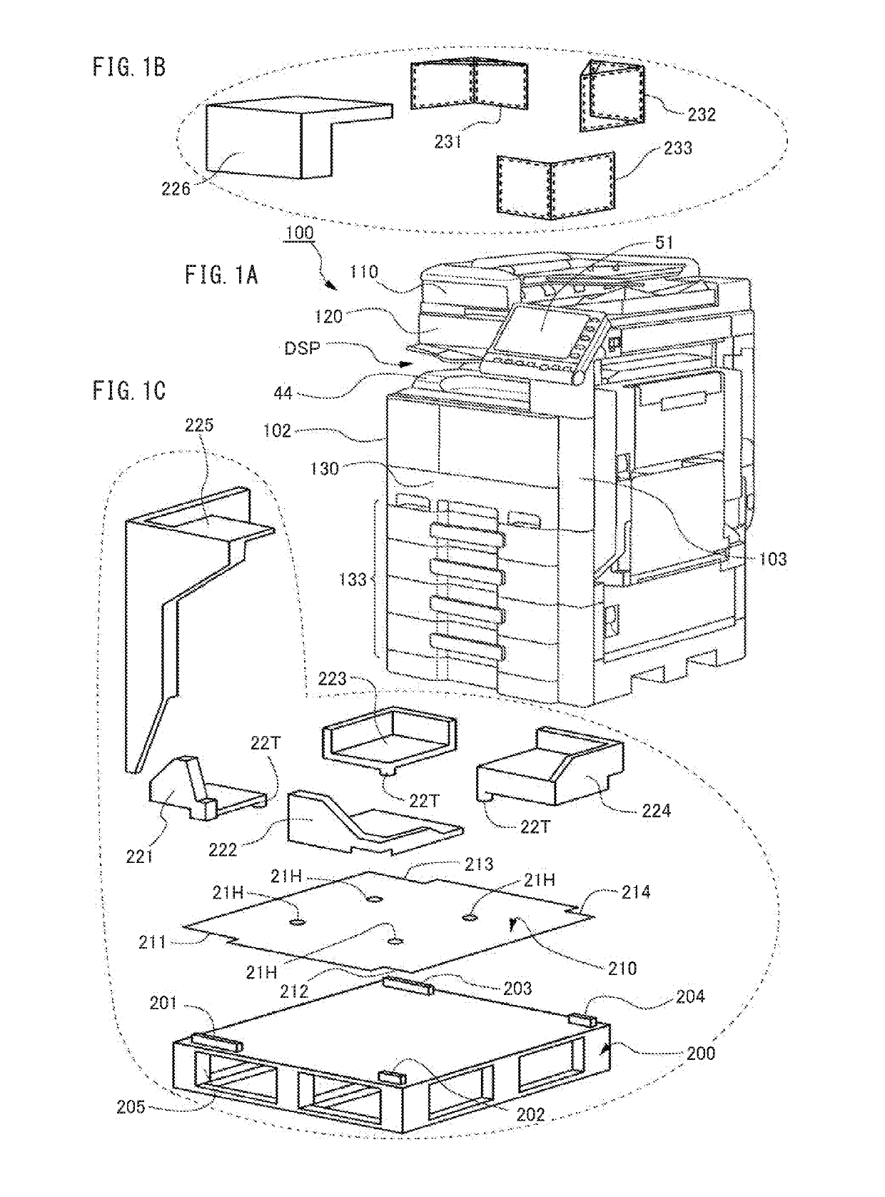
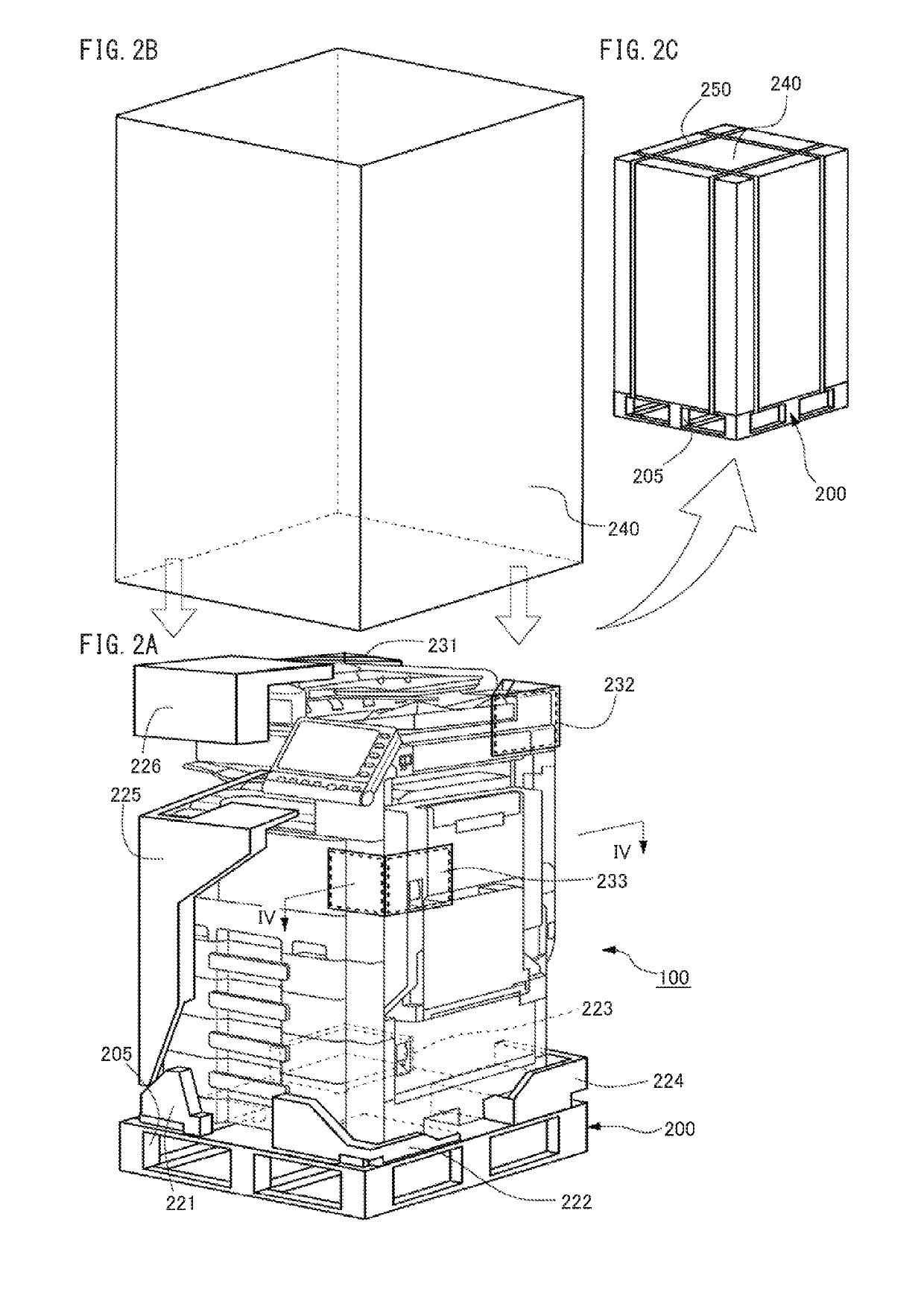
[0024]FIG. 1A is a perspective view of an appearance of an image forming device to be packed. The image forming device 100 is an in-body sheet-ejection type multi-function peripheral (MFP) that has functions of a scanner, a color copier, and a color printer. On an upper face of a housing containing the MFP 100, the MFP 100 has an auto document feeder (ADF) 110 that is mounted in an openable and closable manner. At an upper portion of the housing immediately below the ADF 110 is contained a scanner 120; at a lower portion of the housing is contained a printer 130; and at a bottom portion below the printer 130, the MFP 100 has a plurality of paper cassett...


PUM


Abstract

An air cushion having first and second rooms bends at a partition at a corner of a multi-function peripheral (MFP) and contacts a first face of the MFP at a first room outer surface and a second face of the MFP at an second room outer surface. An outer case applies pressure to the outer surfaces of the first and second rooms and presses the first and second rooms to the MFP. When the first room receives a force from outside the outer case, gas moves from the first room to the second room against pressure the outer case applies to the second room, such that a side wall of the outer case contacting the second room deforms. Upon removal of the force, the side wall returns to an original flat state and presses the second room, such that the gas returns from the second room to the first room.

Description

[0001]This application claims priority to Japanese Patent Application No. 2017-225759 filed Nov. 24, 2017, the contents of which are hereby incorporated herein by reference in its entirety.BACKGROUNDTechnical Field[0002]The present disclosure relates to packing technology, and in particular to cushions.Description of the Related Art[0003]Cushions are indispensable for transportation of components or products vulnerable to external vibrations and shocks, such as high-precision molded components, precision machines, and electronic appliances. Cushions are each a member having high elasticity or plasticity and are placed around an object to be transported, i.e. a package. Specifically, when a package is stored in an outer case made of cardboard, wood, or the like, cushions surround the package or fill gaps between the package and the outer case to support the package inside the outer case. When the outer case receives a vibration or shock from the outside during transportation of the p...

Claims


Application Information

Patent Timeline
Patent Type & Authority Applications(United States)
IPC IPC(8): B65D81/05B65D85/68B65D77/06
CPCB65D85/68B65D77/061B65D2585/689B65D81/052B65D81/054B65D2585/6892
Inventor HASHIMOTO, TAKESHIYOSHIDA, NARUTAKAMIZUGUCHI, HIROMI
Owner KONICA MINOLTA INC
Why Eureka
Try Eureka