Pressure test device for an inflator housing

Inactive Publication Date: 2019-05-30
TOYODA GOSEI CO LTD
View PDF0 Cites 0 Cited by
  • Summary
  • Abstract
  • Description
  • Claims
  • Application Information

AI Technical Summary

Benefits of technology

[0022]With this configuration, if the inflator housing as laid horizontally is moved upward into the heating coil via the void space, the inflator housing is set at the heating position proximate to the heating coil. With this configuration, furthermore, since the setting of the inflator housing at the heating position can be conducted merely by moving the housing upward, a holding member for holding the inflator housing has only to support an underside of the housing, i.e. does not have to be composed of a chucking mechanism or the like that grips the inflator housing. By way of example, the holding member

Problems solved by technology

Pressure resistance of an inflator housing is very important for a secure deployment of the airbag because a problem in pressure resistance may cause a gas leakage.
However, the testing using water requires removal of the water

Method used


Image

  • Pressure test device for an inflator housing
  • Pressure test device for an inflator housing
  • Pressure test device for an inflator housing

Examples


Example

[0031]Preferred embodiments of the present invention are described below with reference to the accompanying drawings. However, the invention is not limited to the embodiments disclosed herein. All modifications within the appended claims and equivalents relative thereto are intended to be encompassed in the scope of the claims.

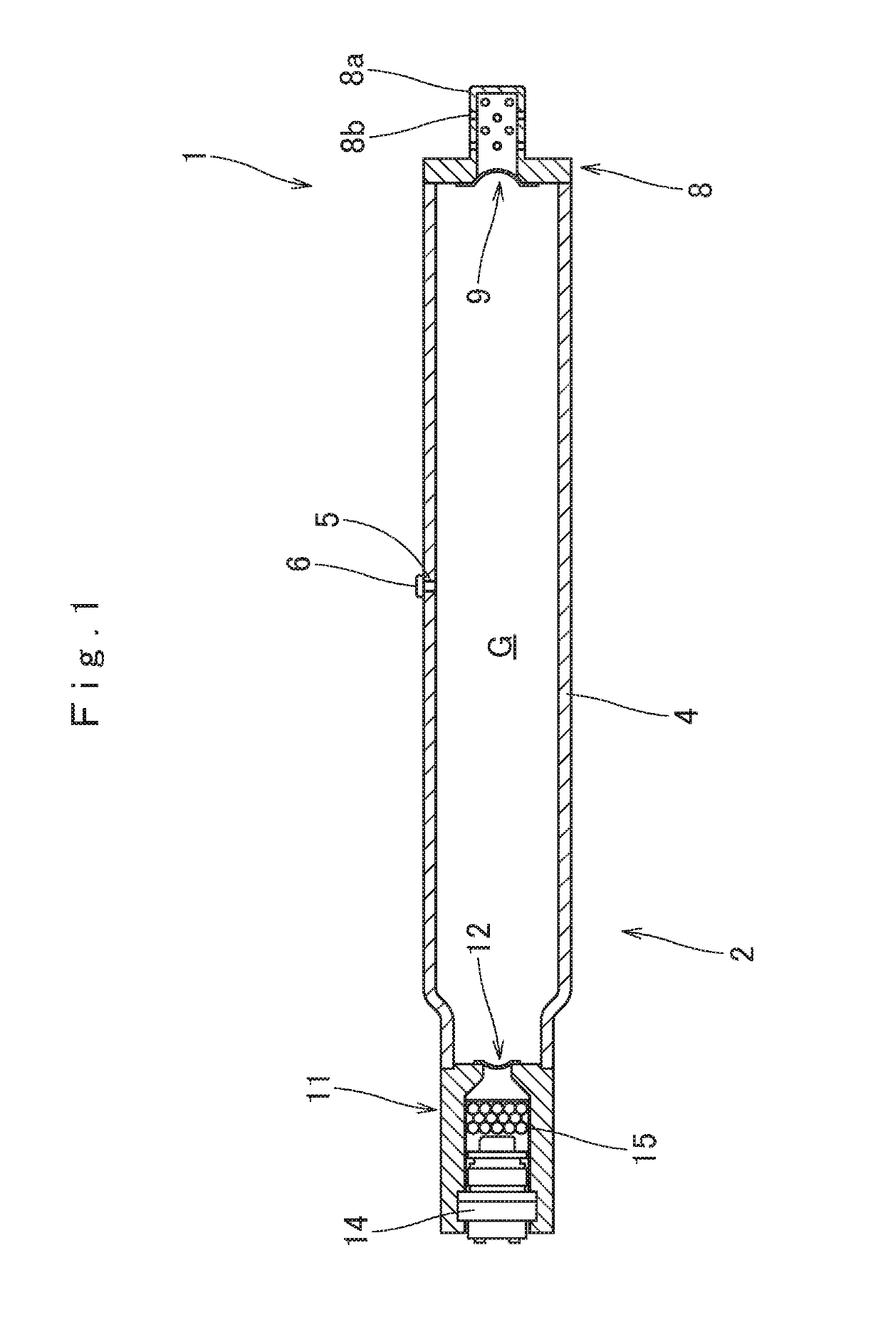
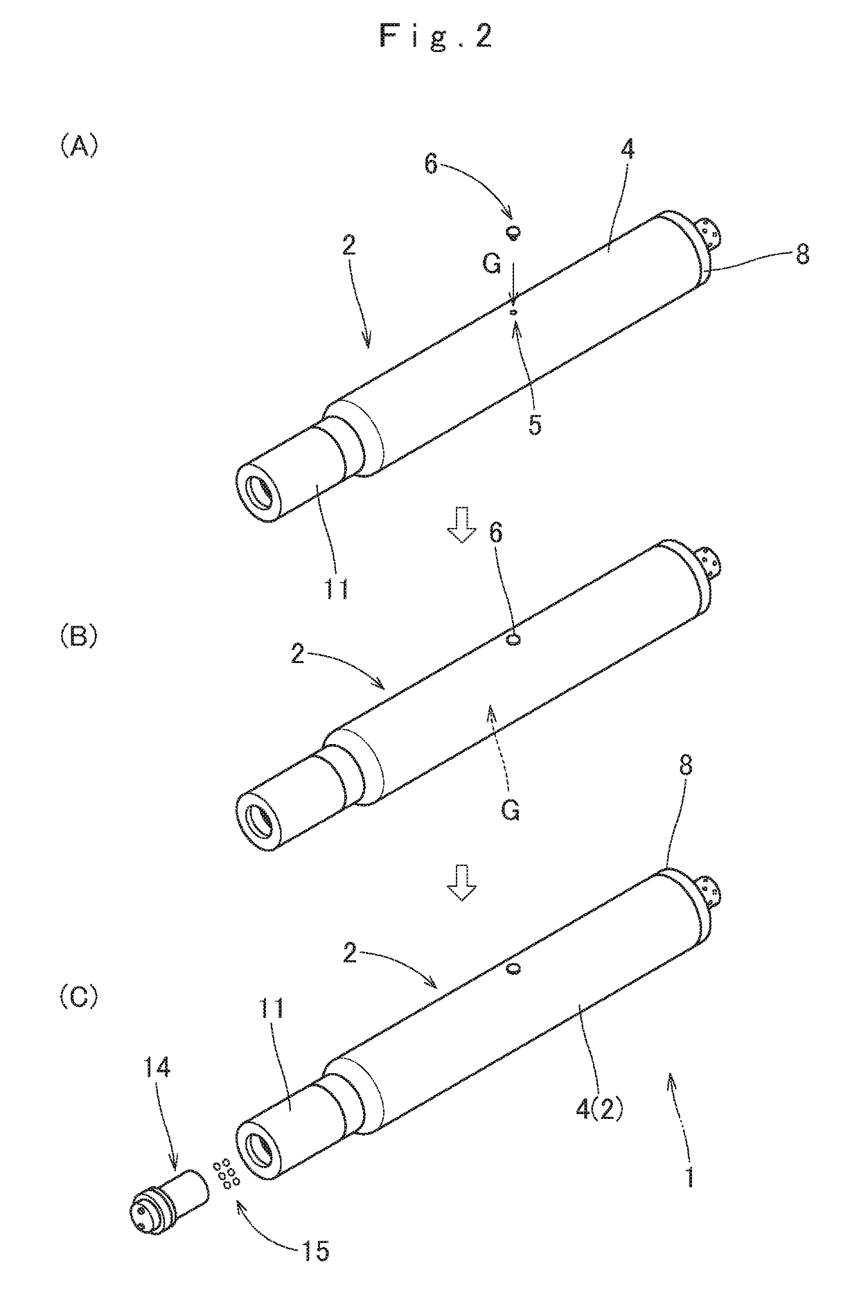
[0032]Firstly, an inflator 1 is described referring to FIGS. 1 and 2. The inflator 1 is formed including an inflator housing 2 which is to be subjected to a pressure test conducted with a pressure test device embodying the invention. The inflator 1 is a hybrid inflator which utilizes a combustion gas generated by burning of propellant and a pressurized gas G of nitrogen, argon or the like inserted in the housing 2 both for inflating an airbag. The housing 2 of the inflator 1 is generally cylindrical in outer contour, and includes a generally cylindrical body 4 having a constricted rear end, a discharging-side end cap 8 which is secured to the front end of the ...


PUM


Abstract

A pressure test device for testing a heat resistance of an inflator housing is disclosed. The inflator housing is made from metal into a generally cylindrical contour and is filled with a gas. The test device includes a heating apparatus for heating the inflator housing. The heating apparatus includes a conducting wire, a heating coil that is connected with the conducting wire and causes induction heating in the inflator housing as set at a heating position, and a power supply that feeds a high-frequency electric current to the conducting wire.

Description

CROSS REFERENCE TO RELATED APPLICATIONS[0001]The Present application claims priority from Japanese Patent Application No. 2017-229664 of Makino et al., filed on Nov. 29, 2017, the entire disclosure of which is incorporated herein by reference.BACKGROUND OF THE INVENTION1. Field of the Invention[0002]The present invention relates to a pressure test device for a housing of an inflator which is used in an airbag device for a vehicle.2. Description of Related Art[0003]Conventionally, an inflator for use in an airbag device is formed by inserting such a gas as a nitrogen gas, in a pressurized form, in a generally cylindrical housing made from such high strength metal as iron. When fed with an actuating signal, a squib and / or a micro gas generator disposed inside the inflator housing is ignited, which initiates burning of propellant. The burnt propellant generates gases, the gasses pressurize the housing, and a burst disc that has partitioned the housing breaks, then the pressurized gases...

Claims


Application Information

Patent Timeline
IPC IPC(8): G01M3/00B60R99/00
CPCG01M3/002B60R99/00B60R2021/26076B60R21/26G01M3/16
Inventor MAKINO, SHUICHIROKINO, YUICHI
Owner TOYODA GOSEI CO LTD
Why Eureka
Try Eureka