

Fluid heating component, and fluid heating component complex
- Summary
- Abstract
- Description
- Claims
- Application Information
AI Technical Summary
Benefits of technology
Problems solved by technology
Method used
Image

Examples
examples
(1) Honeycomb Structure
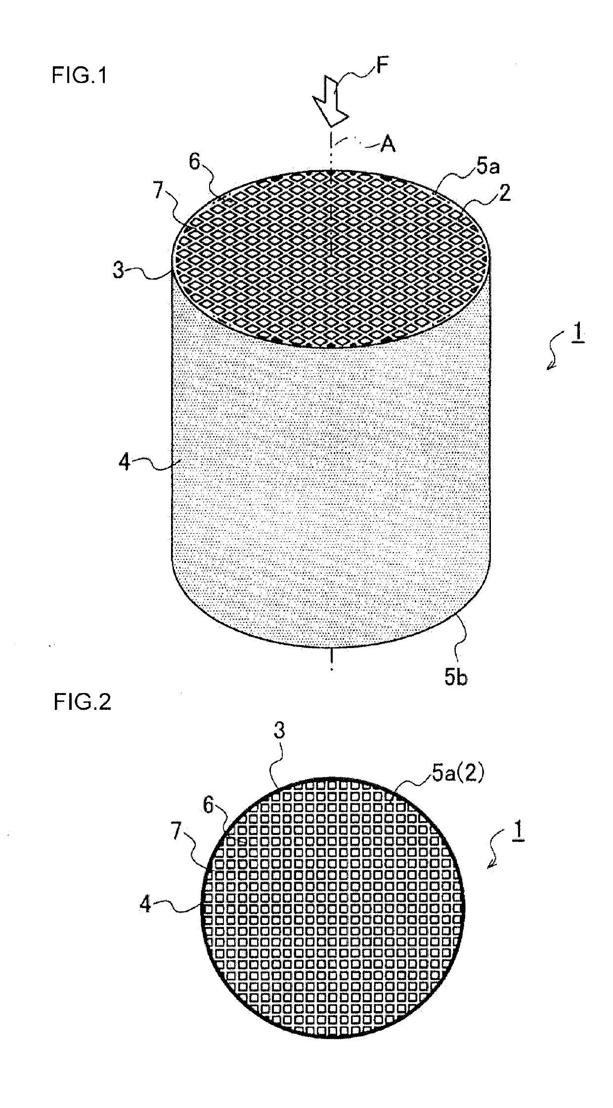
[0080]A honeycomb structure containing SiC as a main component was manufactured. Initially, SiC powder adjusted in a predetermined particle size and in an amount to be prepared, a binder, and water or an organic solvent and others were kneaded to obtain a forming raw material, and the forming raw material was extruded into a desirable shape and dried to obtain a honeycomb formed body. Afterward, the honeycomb formed body was suitably processed, impregnated with Si and fired at a high temperature, to obtain a honeycomb structure. In this case, the honeycomb structure having sizes of a honeycomb diameter of 43 mm and a honeycomb length of 23 mm in an axial direction was used. Furthermore, an impregnation ratio or the like during the Si impregnation and firing was changed, to adjust a porosity of the honeycomb structure to 10% or less in Example 1. Similarly, a porosity of each honeycomb structure was adjusted to 5% or less in Examples 2 to 6 and Comparative Exam...
PUM
| Property | Measurement | Unit |
|---|---|---|
| Thickness | aaaaa | aaaaa |
| Thickness | aaaaa | aaaaa |
| Thermal conductivity | aaaaa | aaaaa |
Abstract
Description
Claims
Application Information