Low CTE slush molds with textured surface, and method of making and using the same

Active Publication Date: 2019-10-08
GENIUS SOLUTIONS ENG
View PDF30 Cites 0 Cited by
  • Summary
  • Abstract
  • Description
  • Claims
  • Application Information

AI Technical Summary

Benefits of technology

[0017]In still yet another embodiment, the shell body has a plurality of fins or grooves on the backside

Problems solved by technology

One drawback associated with the use of nickel molds produced in this manner is that the mold can have an unpredictable, and often relatively short life cycle.
The primary failure mode in nickel shell cast skin tooling is the accumulated residual stresses resulting from thermal cycling.
The thermal cycle stress is a result of the material manufacturing process and the CTE (coefficient of thermal expansion) of the material which over time results in a crack in the nickel mold.
This is due to the non-uniform mold thickness resulting from the manufacturing procedure.
These thicker areas will expand at different rates across the mold surface during heating and cooling and this thickness variation can produce stress over time that results in the shell failure.
The shell failure is often caused by shell cracking.
For instance, in applications utilizing oil to heat

Method used


Image

  • Low CTE slush molds with textured surface, and method of making and using the same
  • Low CTE slush molds with textured surface, and method of making and using the same
  • Low CTE slush molds with textured surface, and method of making and using the same

Examples


Example

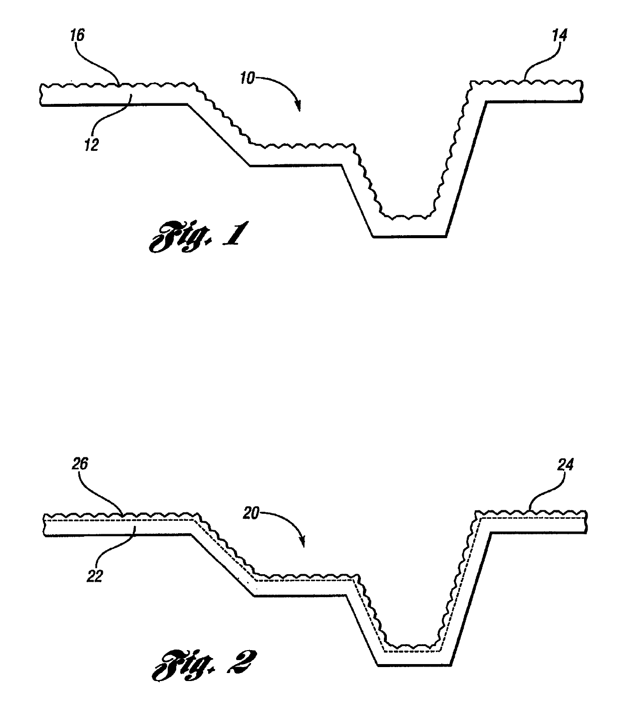
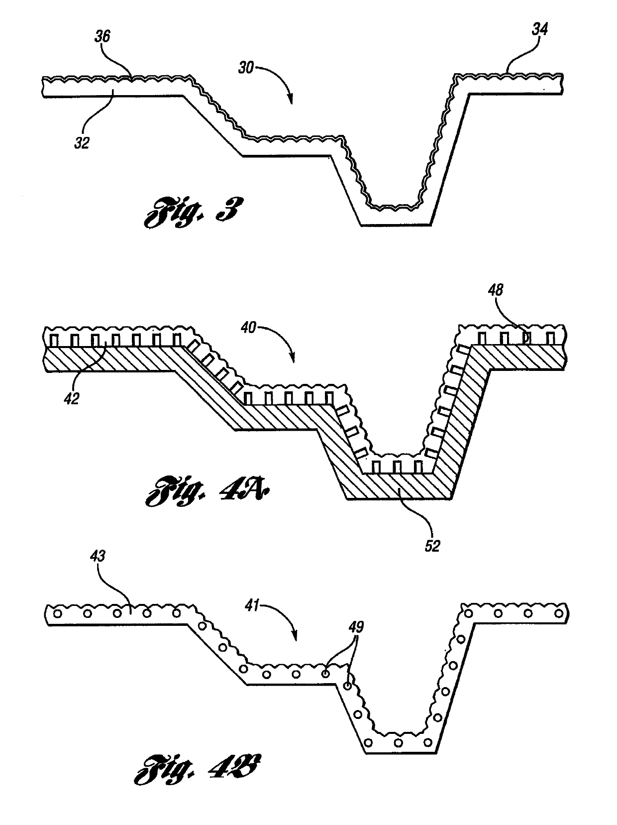
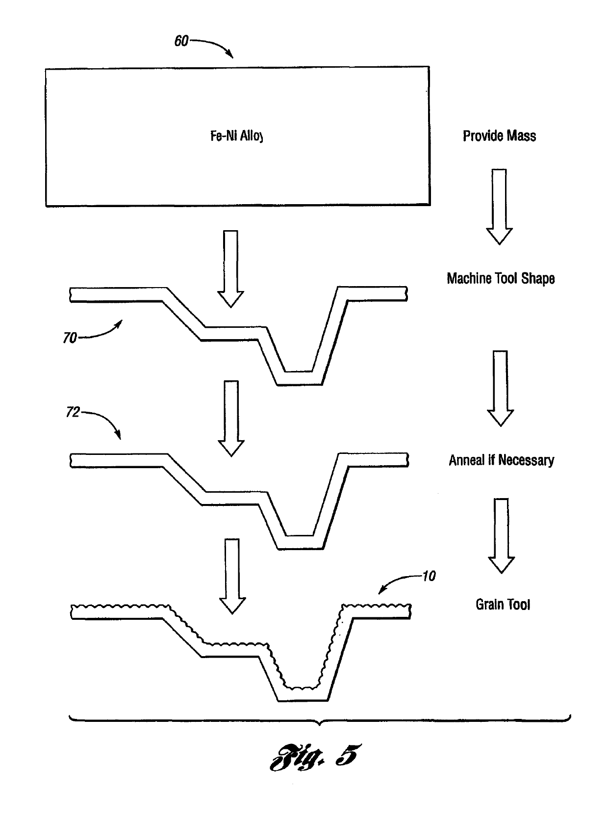
[0056]As required, detailed embodiments of the present invention are disclosed herein; however, it is to be understood that the disclosed embodiments are merely exemplary of the invention that may be embodied in various and alternative forms. The figures are not necessarily to scale; some features may be exaggerated or minimized to show details of particular components. Therefore, specific structural and functional details disclosed herein are not to be interpreted as limiting, but merely as a representative basis for teaching one skilled in the art to variously employ the present invention.

[0057]Except in the examples, or where otherwise expressly indicated, all numerical quantities in this description indicating amounts of material or conditions of reaction and / or use are to be understood as modified by the word “about” in describing the broadest scope of the invention.

[0058]It is also to be understood that this invention is not limited to the specific embodiments and methods desc...


PUM

PropertyMeasurementUnit
Temperatureaaaaaaaaaa
Thicknessaaaaaaaaaa

Abstract

A rotomolding tool having a textured surface is provided. The tool comprises a shell having a body portion and an upper mold surface having a grain texture, at least the body portion comprising a nickel-iron alloy having a coefficient of thermal expansion of at most 5.O×10−6 in/in/° F. at temperatures between 100° and 500° F.

Description

CROSS-REFERENCE TO RELATED APPLICATION[0001]This application is the U.S. national phase of PCT Appln. No. PCT / US2010 / 038291 filed Jun. 11, 2010 which claims the benefit of U.S. provisional application Ser. No. 61 / 268,369 filed Jun. 11, 2009, the disclosures of which are incorporated in their entirety by reference herein.TECHNICAL FIELD[0002]The present invention relates to molds useable for slush molding made of a material with a low coefficient of thermal expansion in the molding temperature range. The present invention also relates to methods of making and using the molds.BACKGROUND[0003]In at least one embodiment, the present invention is used for slush molding parts for use in the automotive industry. Slush molding is commonly utilized in the automotive industry to produce “class A” interior skins, which are used in the automobile interior, such as for instrument and door panels. A typical slush molding process involves casting a charge of powder polymeric material against a hea...

Claims


Application Information

Patent Timeline
IPC IPC(8): B29C41/18C23C8/26C23C8/24B29C41/46B29C41/38B29C33/42B29C33/02C23C8/02B29C33/56C23C2/28C23C2/12B29C33/04B29L31/30
CPCC23C8/26B29C33/424B29C41/46C23C2/12C23C2/28C23C8/24C23C8/02B29C41/38B29C33/02B29C33/565B29C41/18B29C2033/042B29L2031/3005C23C2/261
Inventor SHADE, MATTHEW MARTINGRINBERG, GRIGORIY
Owner GENIUS SOLUTIONS ENG
Why Eureka
Try Eureka