Temperature adjustment stage

Pending Publication Date: 2021-03-11
OTSUKA PHARM CO LTD
View PDF0 Cites 0 Cited by
  • Summary
  • Abstract
  • Description
  • Claims
  • Application Information

AI Technical Summary

Benefits of technology

[0026]According to the temperature adjustment stage of the present invention, the ca

Problems solved by technology

Therefore, temperature inside the sensor chip is greatly affected by temperature of the i

Method used


Image

  • Temperature adjustment stage
  • Temperature adjustment stage
  • Temperature adjustment stage

Examples


Example

[0034]Hereinafter, a temperature adjustment stage according to a first embodiment of the present invention will be described with reference to the drawings, with a temperature adjustment stage for heating a cartridge as an example. Note that the cartridge is used for an inspection system for surface plasmon-field enhanced fluorescence spectroscopy (SPFS) measurement and the like.

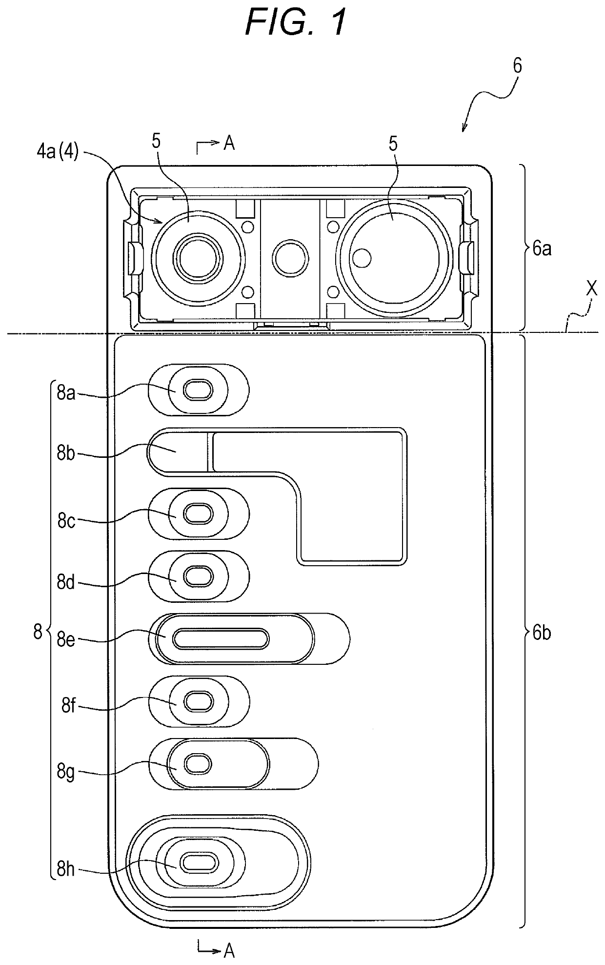
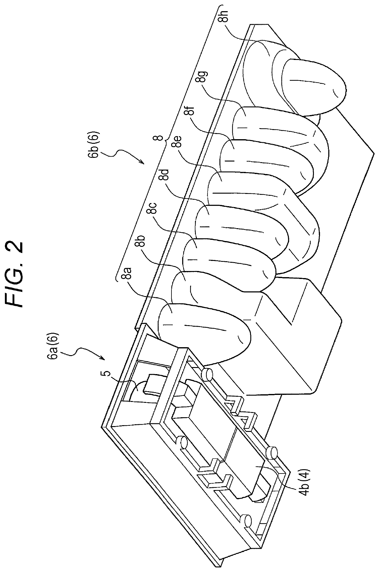
[0035]FIG. 1 is a plan view showing a front surface of the cartridge according to the first embodiment, and FIG. 2 is a perspective view of the cartridge viewed from a back surface side. As shown in FIGS. 1 and 2, a cartridge 6 is a rectangular member in plan view including an arrangement part 6a and a well formation part 6b as shown in FIGS. 1 and 2, and is formed by a resin member such as polystyrene or polypropylene. Note that a straight line X shown in FIG. 1 indicates a boundary between the arrangement part 6a and the well formation part 6b.

[0036]The arrangement part 6a is made by an opening formed at ...

Example

[0069]Next, a temperature adjustment stage according to a second embodiment will be described. The second embodiment is a modification of the first embodiment, and therefore, portions different from the first embodiment will be described in detail, and description of overlapping portions will be omitted.

[0070]FIG. 6 is a cross-sectional view showing a state where a cartridge according to the second embodiment is mounted on a temperature adjustment stage according to the second embodiment. As shown in FIG. 6, on a back surface 10a of a temperature adjustment stage 101, a recessed part 15 (recess) is provided instead of the non-contact recess 13 of the first embodiment.

[0071]Here, similarly to the non-contact recess 13, the recessed part 15 is provided immediately below a well 8 that does not need to be heated. Note that, unlike the non-contact recess 13, the recessed part 15 penetrates to the back surface 10a of the temperature adjustment stage 10 and has high heat insulation, and th...

Example

[0072]Next, a temperature adjustment stage according to a third embodiment will be described. The third embodiment is a modification of the first embodiment, and therefore, portions different from the first embodiment will be described in detail, and description of overlapping portions will be omitted.

[0073]FIG. 7 is a cross-sectional view showing a state where a cartridge according to the third embodiment is mounted on a temperature adjustment stage according to the third embodiment. As shown in FIG. 7, in a cartridge 6′ according to the third embodiment, a labeled antibody liquid well 8c is arranged away from a position of a sensing member 4. Specifically, wells 8 are arranged, from the sensing member 4 side, in the order of a cleaning liquid well 8e, a mixed diluent well 8f, a specimen diluent well 8g, a measurement reagent well 8a, a spare well 8d, a waste liquid well 8b, the labeled antibody liquid well 8c, and a specimen holding well 8h.

[0074]In this way, by arranging the lab...


PUM


Abstract

To provide a temperature adjustment stage that can efficiently heat a cartridge in accordance with necessity of heating each well. A temperature adjustment stage for heating a cartridge in which a plurality of wells that store a liquid are formed. The cartridge is used in an inspection system that detects an object captured by an immunoreaction, the wells include a labeled antibody well that stores a labeled antibody that labels the object, and there is provided a structure that does not heat the labeled antibody well.

Description

TECHNICAL FIELD[0001]The present invention relates to a temperature adjustment stage for heating a cartridge used in an inspection system that detects an object captured by an immunoreaction.BACKGROUND ART[0002]Conventionally, it is known that biochemical reactions and immunoreaction are greatly affected by temperature. For example, in a fully automatic biochemical reaction device or immunoreaction device using a sensor chip, a reagent such as a reaction solution and a cleaning liquid is sequentially introduced into the sensor chip inside the device. Therefore, temperature inside the sensor chip is greatly affected by temperature of the introduced reagent.[0003]Here, since it is known that temperature inside the sensor chip (reaction field) is greatly affected by temperature of the reagent used, it is necessary to control the reagent temperature.[0004]As the reagent temperature, various cases are assumed such as after being adapted to temperature of surroundings, that is, temperatur...

Claims


Application Information

Patent Timeline
IPC IPC(8): B01L7/00G01N21/03G01N21/41G01N31/22
CPCB01L7/00G01N31/22G01N21/41G01N21/03G01N35/00B01L2200/16B01L2300/1805B01L2300/185B01L2300/1844B01L3/50851
Inventor MIYAZAKI, KOJIFUJII, HIDEYUKIOSAWA, KOMURAYAMA, TAKANORI
Owner OTSUKA PHARM CO LTD
Why Eureka
Try Eureka