
Decorative radiator

Inactive Publication Date: 2006-08-15
STROOBANTS MARCEL +1
View PDF12 Cites 1 Cited by
  • Summary
  • Abstract
  • Description
  • Claims
  • Application Information

AI Technical Summary

Benefits of technology

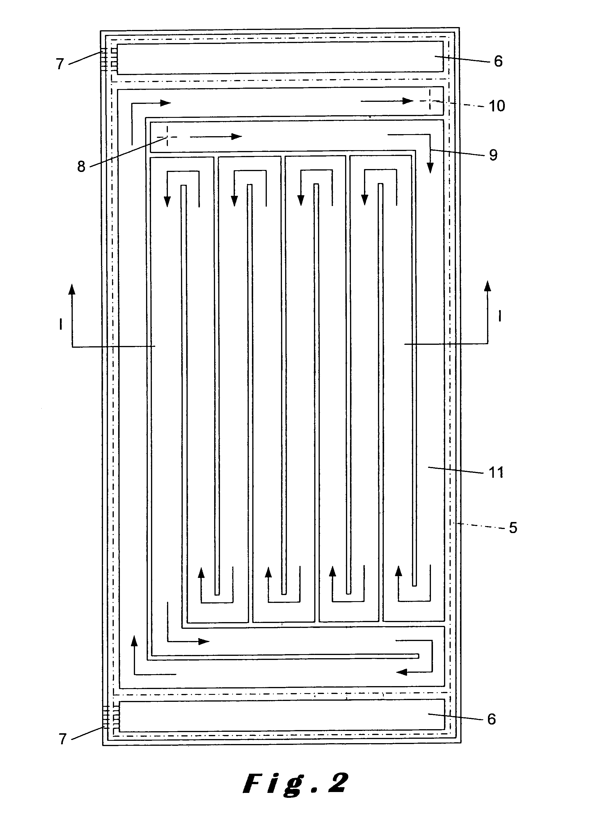
[0022]It is an aim of the Invention to avoid those disadvantages by realising a controlled flow of hot water, which is achieved by a developed system of canals.
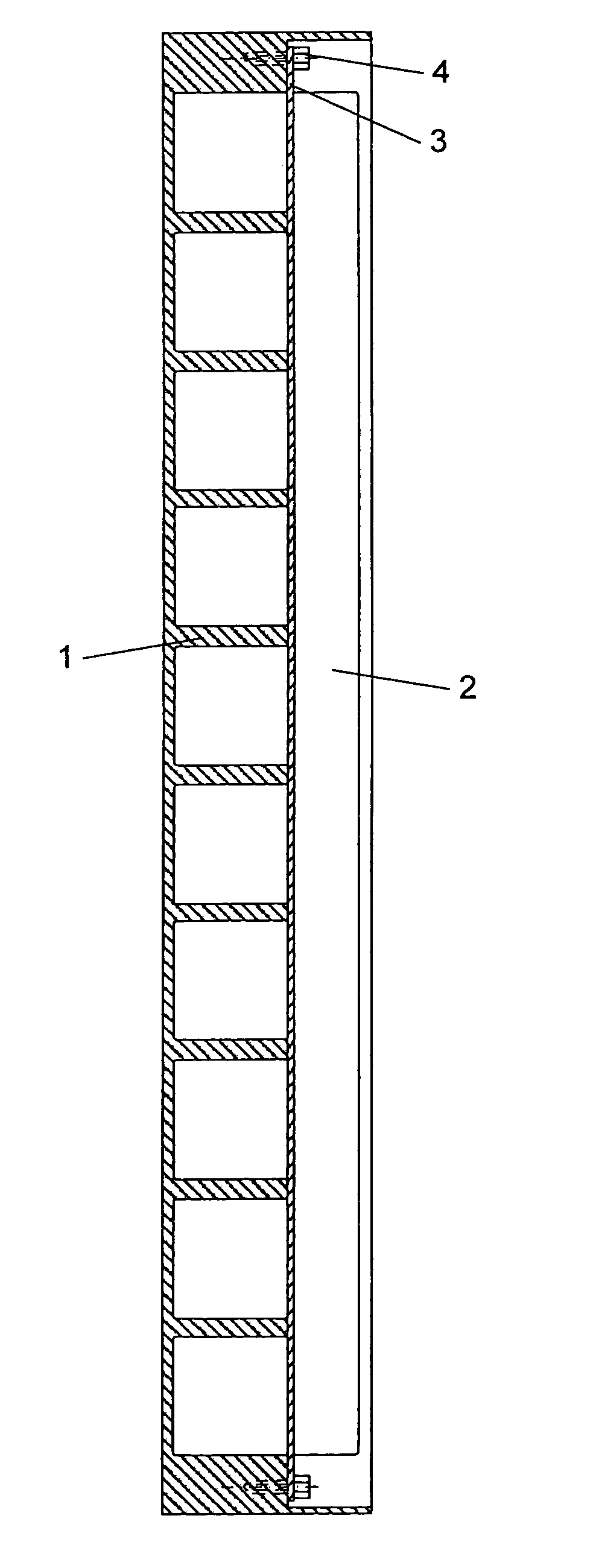
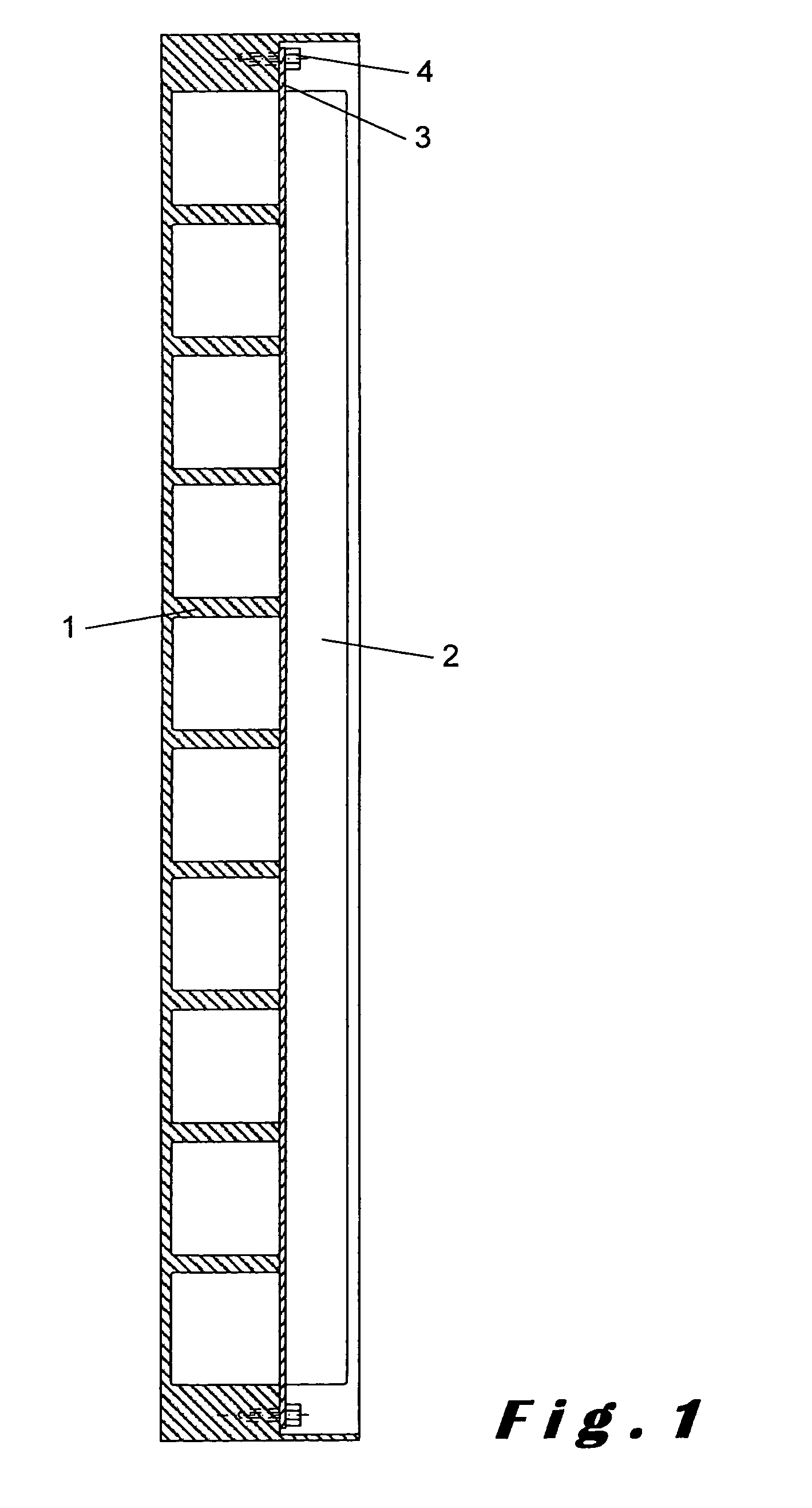
[0025]The front panel preferably comprises slots on top, through which the hot air may be evacuated from the back panel. On the sides, the front panel may comprise hollow spaces, which form cavities with the back panel for use as water containers. Due to the heating, these water containers will function as air humidifiers. The openings on top of these humidifiers, which are provided for dispensing water vapour may be located in a detachable cap, so that the humidifier can be refilled and cleaned.
[0028]The entry of hot water into the preformed canals of the front panel is preferably located as high as possible. This has the advantage that a thermal supply tap which is connected on the supply fitting can be controlled more comfortably. The preformed canals are preferably provided for causing a warming-up effect in ascending direction, which can make the heating more efficient. Furthermore, the preformed canals are preferably provided for guiding the cooled water through the parts of the radiator which are “touchable”, so that the danger of bums can be limited.

Problems solved by technology

Such a complex production line needs high-costs investments.
Meanwhile the produce of heat, which begins at the top of the radiator, has no optimal effect: the water becomes colder in its way down, which doesn't stimulate the circulation of air and the heat.

Method used


Image

  • Decorative radiator
  • Decorative radiator
  • Decorative radiator

Examples


Embodiment Construction

[0036]The use of the coloured synthetic granules by the fabrication of “the body” of the radiator (see FIG. 1—part 1) allows us to make a large range of different colours. We remark that the synthetic materials will be effectively coloured, which will not reveal a slight damage.

[0037]It is clear that the fact of No PAINTING will lead to a considerable cost saving and a less cause of environmental damage. (no painting installation is needed).

[0038]The total weight of the radiator will be considerably less than a “classic radiator” of the the same measurements, a fact which the installers will not regret.

[0039]The decorative radiator can be realised in all kinds of colours, forms and shapes. The front side (visible side) of the front panel can be flat, on which every design, modern or classical, black and white or in one or different colours, using several print techniques.

[0040]The front side can be fabricated with a bas-relief, expressing a classic or modern theme and, if it's the c...


PUM

PropertyMeasurementUnit
Electrical conductoraaaaaaaaaa

Abstract

A radiator is disclosed for mounting in an upright position to a wall, comprising a front panel and a back panel between which an interior space is provided for introducing a fluid. The back panel is made of a heat-conductive material and is provided with fluid supply and drainage fittings for supplying and draining the fluid to and from said interior space. The back panel is further provided with cooling ribs for exchanging heat with surrounding air and mounting brackets for mounting the radiator on a wall. The front panel has pre-formed canals for directing the fluid flow in a controlled way from the supply fitting to the drainage fitting. The front panel is made of a synthetic material which is substantially non-heat-conductive. A seal is provided between the panels for making said interior space substantially fluid-tight. The front and back panels are assembled with the seal in between by means of bolts.

Description

CROSS-REFERENCE TO RELATED APPLICATIONS[0001]This applications claims the priority of International Application No. PCT / BE01 / 00213, filed Dec. 14, 2001, which claims the priority of Belgium Patent No. 2000 / 0791, filed Dec. 15, 2000, both of which are incorporated herein by reference in their entireties.BACKGROUND OF THE INVENTION[0002]The market of radiators, based on the input of warm water, in domestic use, is divided in 2 main groups:[0003]a) radiators made of steel plate and mostly manufactured in a mass production;[0004]b) so called “design radiators”, made basically of different kinds of tubes, whose forms and measures are targeted to the clients' wish.[0005]To produce them, the radiators as described in a) need main investments, starting from a plate of steel, cut in the desired forms, in which “canals” are being pressed, whereupon the radiator is formed by a specific welding process, to make them waterproof.[0006]In most cases, several radiators are connected as a whole unit...

Claims


Application Information

Patent Timeline
IPC IPC(8): F28F3/12F24D19/02F24H9/02F24F1/00F24D19/00F24F5/00F24F6/00F28D1/00F28D1/03F28F3/00F28F3/02F28F21/06F28F21/08
CPCF24D19/0082F28D1/035F28F21/088F28F21/066F28D2001/0286F28D2021/0035F28D2001/0293
Inventor STROOBANTS, MARCELVERCAUTEREN, PIERRE
Owner STROOBANTS MARCEL
Learn More