
Over-the-air test system and method for testing a device under test

a test system and test method technology, applied in the direction of digital circuit testing, electronic circuit testing, measurement devices, etc., can solve the problem of high cost of determining the receiving properties of the device under test, and achieve the effect of simple and cost-efficien

Active Publication Date: 2019-05-30
ROHDE & SCHWARZ GMBH & CO KG
View PDF5 Cites 16 Cited by
  • Summary
  • Abstract
  • Description
  • Claims
  • Application Information

AI Technical Summary

Benefits of technology

The patent text describes a need for a test system and method to test devices in a wireless communication environment for both transmission and receiving properties in a cost-efficient and easy manner. The system uses an over-the-air test and a measurement antenna with beam steering to simulate different base stations and conditions. The system also includes a signal attenuation unit to suppress interfering signals. The test system enables testing the device under test in different directions and with different data.

Problems solved by technology

Due to the complex test system, the costs for determining the receiving properties of the device under test are high.

Method used


Image

  • Over-the-air test system and method for testing a device under test
  • Over-the-air test system and method for testing a device under test

Examples


Embodiment Construction

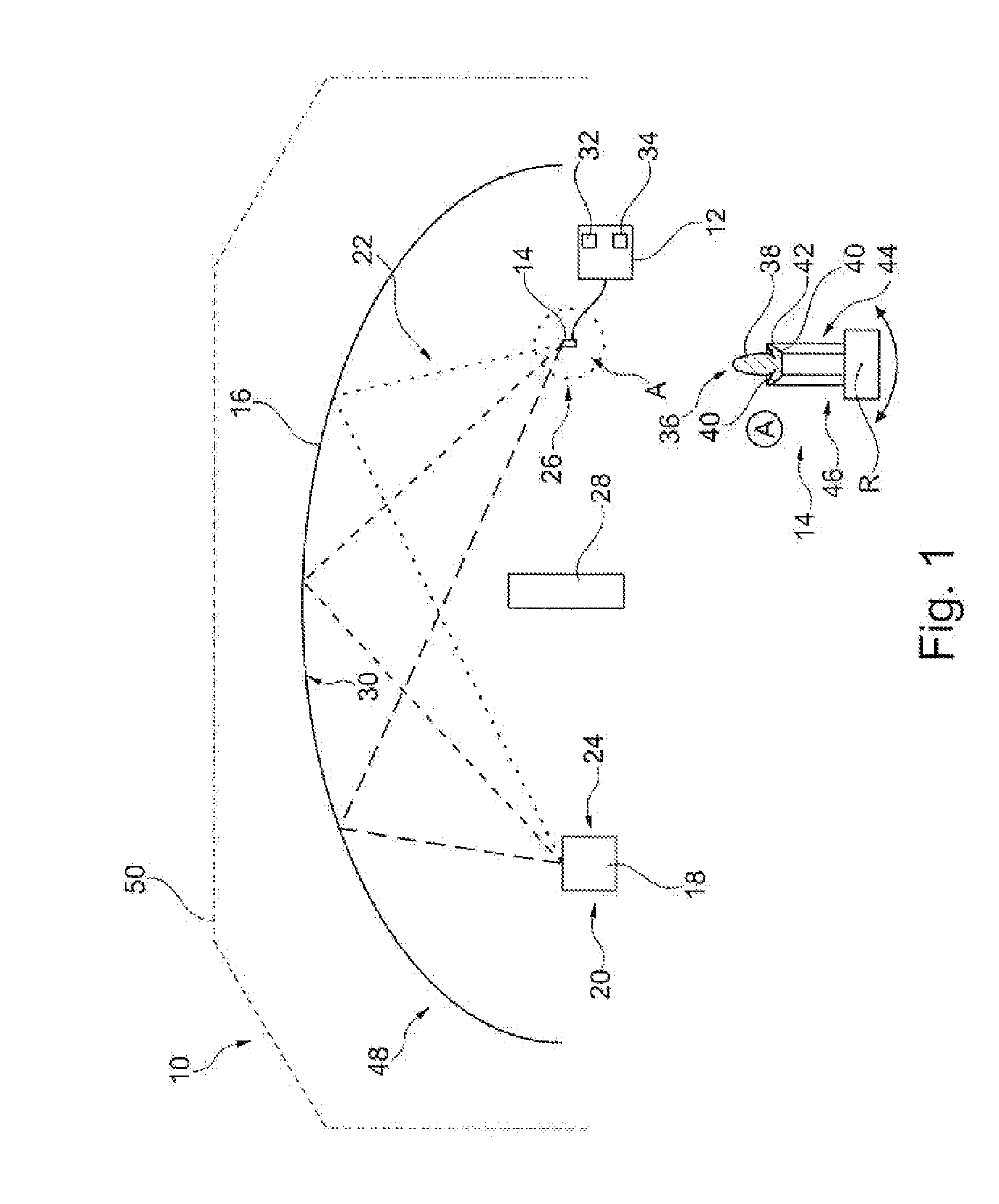
[0049]In FIG. 1, an over-the-air (OTA) test system 10 is shown that comprises a signal processing unit 12 that is connected with a measurement antenna 14 which receives and / or transmits a signal. Therefore, the signal processing unit 12 is configured to analyze a signal received via the measurement antenna 14 and / or to generate a signal to be transmitted via the measurement antenna 14.

[0050]Further, the test system 10 comprises a reflector 16 for reflecting electromagnetic signals that are used for testing purposes. The reflector 16 is positioned between the measurement antenna 14 and a device under test 18 to be tested which is positioned at a testing location 20 of the test system 10. In fact, the testing location 20 corresponds to a fixed location with respect to the reflector 16. Accordingly, a signal path 22 is established between the device under test 18 and the measurement antenna 14 along which the signals are exchanged. The reflector 16 is positioned in the signal path 22 f...


PUM


Abstract

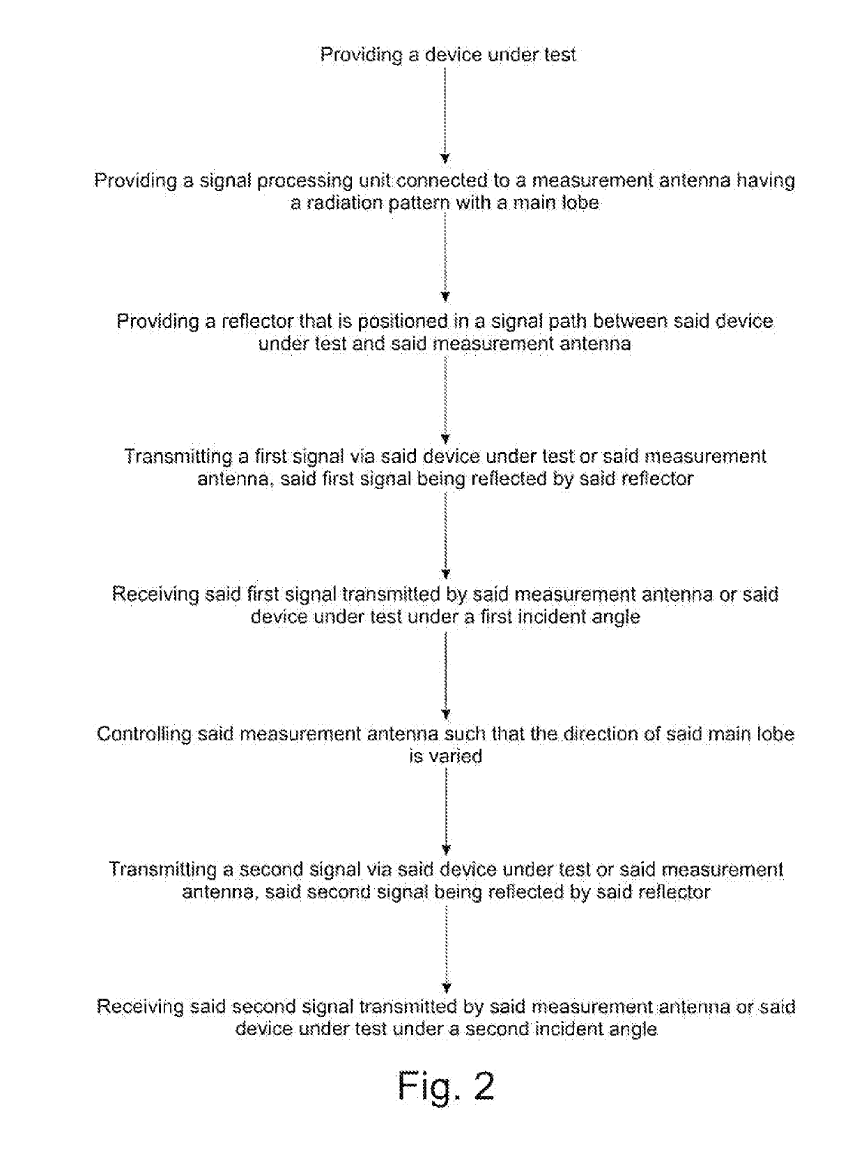
An over-the-air test system is described that is used for testing a device under test in a wireless communication environment. The test system comprises at least one measurement antenna connected with a signal processing unit configured to generate a signal or to analyze a signal. The test system further comprises a reflector configured to reflect electromagnetic signals, the reflector being positioned in a signal path established between the device under test and the measurement antenna such that the signals are reflected by the reflector. The measurement antenna has a radiation pattern with a main lobe, the measurement antenna being configured to adjust the direction of the main lobe with respect to the reflector in order to simulate different impinging angles of the signals. Further, a method for testing a device under test is described.

Description

FIELD OF THE DISCLOSURE[0001]Embodiments of the present disclosure relate generally to an over-the-air test system for testing a device under test in a wireless communication environment. Further, embodiments of the present disclosure relate to a method for testing a device under test with an over-the-air test system for testing a device under test in a wireless communication environment.BACKGROUND[0002]Over-the-air test systems for testing communication devices are known, for instance for testing mobile communication devices such as mobile phones or tablets. These communication devices to be tested correspond to devices under test wherein the communication properties of the devices under test are evaluated by the test system appropriately, in particular the transmission and / or receiving properties of the communication devices.[0003]It is known to investigate the transmission properties of the device under test by transmitting test signals via the device under test, which are receiv...

Claims


Application Information

Patent Timeline
IPC IPC(8): G01R31/302G01R31/307G01R31/317G01R31/28
CPCG01R31/3025G01R31/307G01R31/317G01R31/2841H04B17/29
Inventor DANZ, JOACHIM
Owner ROHDE & SCHWARZ GMBH & CO KG
Learn More