
Thermal management system for vehicle

a technology of management system and vehicle, applied in the direction of vehicle sub-unit features, battery/fuel cell control arrangement, transportation and packaging, etc., can solve the problems of durability and noise, deterioration of cooling performance and efficiency, etc., to reduce noise in the interior, improve cooling capacity, and improve performance and efficiency.

Active Publication Date: 2019-06-06
HANON SYST
View PDF0 Cites 8 Cited by
  • Summary
  • Abstract
  • Description
  • Claims
  • Application Information

AI Technical Summary

Benefits of technology

The present invention provides a thermal management system for a vehicle that has a compact refrigerant circuit and reduces noise inside the vehicle. This system can be placed in various locations on the outer face of the vehicle, such as the front or lower portions. Compared to existing air-cooled systems, the present invention has better performance and efficiency as it reduces the back flow of air. The system also has a flexible radiation part that can be easily increased in size. Increasing the cooling capacity is easier with the water-cooled condenser. The system reduces the number of connection portions among components, decreases costs, and improves efficiency and productivity.

Problems solved by technology

In addition, the conventional thermal management system, which has the structure for inhaling and discharging outdoor air in one module, has another problem in that cooling performance and efficiency are deteriorated since the heated air flows back and is inhaled, and in that it has weak points in durability and noise due to high pressure generated in the system if outdoor air temperature is high.

Method used


Image

  • Thermal management system for vehicle
  • Thermal management system for vehicle
  • Thermal management system for vehicle

Examples


Embodiment Construction

[0039]Hereinafter, a technical structure of a thermal management system for a vehicle according to the present invention will be described in detail with reference to the accompanying drawings.

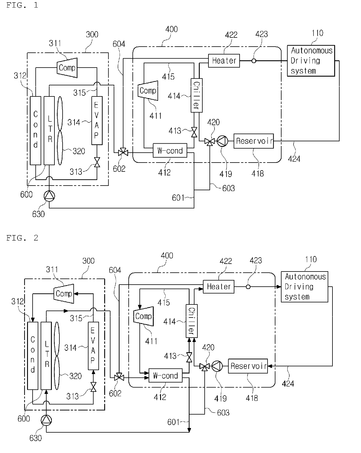
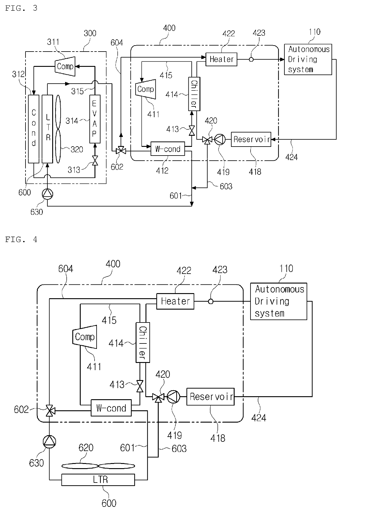
[0040]FIG. 1 is a view of a thermal management system for a vehicle according to a first preferred embodiment of the present invention, FIG. 2 is a view showing a chiller cooling mode of the thermal management system for a vehicle according to the first preferred embodiment of the present invention, and FIG. 3 is a view showing a radiator cooling mode of the thermal management system for a vehicle according to the first preferred embodiment of the present invention.

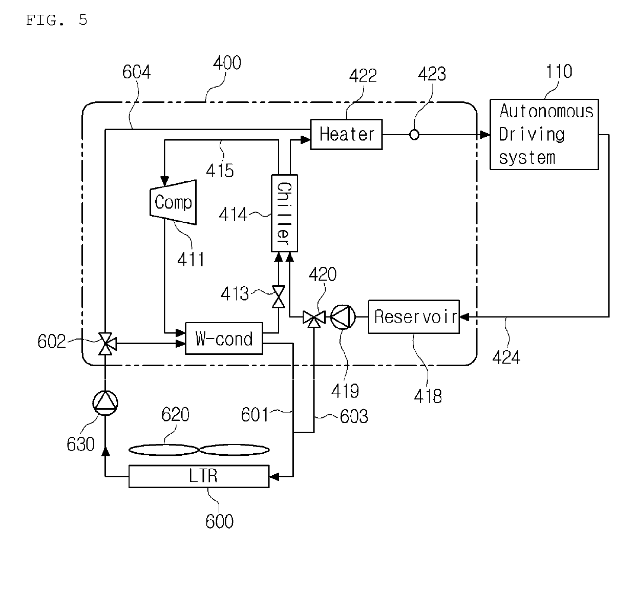
[0041]As shown in FIGS. 1 to 3, the thermal management system for the vehicle according to the first preferred embodiment of the present invention is to perform a series of thermal managements to cool or heat electronic components (electronic devices 110), such as a computer, a lidar, a radar, and a sensor of an autonomous vehicle, ...


PUM


Abstract

The present invention relates to a vehicle thermal management system which is separately provided with the final heat dissipation unit of a cooling system for cooling electronic components required for the autonomous driving of a vehicle, optimizes the modularization of units, and thereby promotes the reduction of a package.

Description

TECHNICAL FIELD[0001]The present invention relates to a thermal management system for a vehicle, and more particularly, to a thermal management system for a vehicle capable of cooling or heating electronic devices for an autonomous system.BACKGROUND ART[0002]In general, an autonomous system for a vehicle includes electronic devices, such as a lidar, a radar, a sensor, and so on. For autonomous driving of the vehicle, a series of thermal managements for cooling or heating electric parts including the electronic devices are essentially demanded.[0003]In the meantime, U.S. Pat. No. 7,841,431 (Nov. 30, 2010) discloses a thermal management system for a vehicle including power train cooling subsystem, a refrigeration subsystem, a battery cooling subsystem, and a heating, ventilation and cooling (HVAC) subsystem.[0004]A conventional thermal management system for a vehicle includes a cooling subsystem, an HVAC subsystem having a first refrigerant loop having a heating means and a cooling me...

Claims


Application Information

Patent Timeline
Patent Type & Authority Applications(United States)
IPC IPC(8): B60H1/00B60H1/22B60H1/32B60K11/02B60R16/03
CPCB60H1/00492B60H1/22B60H1/00278B60H1/32B60K11/02B60R16/03B60H2001/00307B60H2001/006B60Y2306/05B60H1/00B60H1/32284B60H2001/00928B60H1/143B60H1/32281B60L58/26B60H1/00885B60H1/00271B60H1/3227B60H1/00807
Inventor LEE, HAE JUNLEE, SUNG JEJIN, HYEONG KYU
Owner HANON SYST
Learn More