Battery diagnosis method, battery diagnosis program, battery management apparatus, and power storage system

a battery management and battery technology, applied in secondary cells, battery servicing/maintenance, instruments, etc., can solve the problems of large-scale tasks, increased cost, and external measurement of the internal resistance of each cell using a dedicated diagnosis apparatus after the operation of the secondary, and achieve the effect of low cos

Active Publication Date: 2019-06-06
PANASONIC INTELLECTUAL PROPERTY MANAGEMENT CO LTD
View PDF0 Cites 8 Cited by
  • Summary
  • Abstract
  • Description
  • Claims
  • Application Information

AI Technical Summary

Benefits of technology

[0010]According to the present disclosure, it is possible to simply perform the separation analysis of the internal resistance of a secondary battery at a low cost.

Problems solved by technology

When the oscillator is mounted in a battery management apparatus, the cost is increased.
Although a dedicated diagnosis apparatus including the oscillator may be used, external measurement of the internal resistance of each cell using the dedicated diagnosis apparatus after the operation of the secondary battery is started is a large-scale task.
Accordingly, it is inconvenient for a user to perform the deterioration diagnosis using the alternating current impedance method after the operation of the secondary battery is started.

Method used


Image

  • Battery diagnosis method, battery diagnosis program, battery management apparatus, and power storage system
  • Battery diagnosis method, battery diagnosis program, battery management apparatus, and power storage system
  • Battery diagnosis method, battery diagnosis program, battery management apparatus, and power storage system

Examples


Embodiment Construction

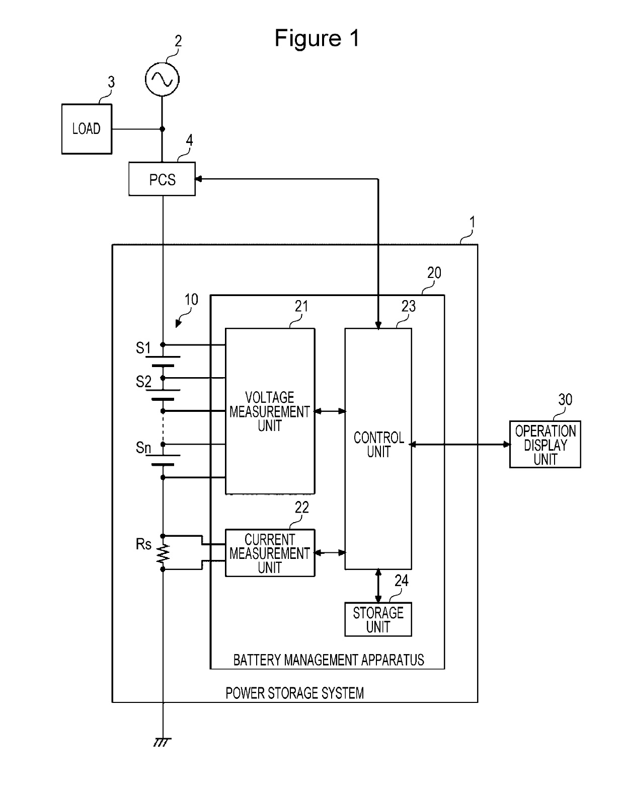
[0022]FIG. 1 is a diagram illustrating an exemplary configuration of a power storage system 1 according to an embodiment of the present invention. The power storage system 1 illustrated in FIG. 1 is an exemplary configuration of the stationary power storage system 1. The power storage system 1 includes a battery module 10 and a battery management apparatus 20. The battery module 10 is composed of multiple cells S1 to Sn that are connected in series to each other. The battery module 10 may be composed of multiple cells that are connected in parallel to each other or that are connected in series and parallel to each other. It is assumed in the present embodiment that a rectangular or cylindrical lithium ion battery (nominal voltage: 3.6 V to 3.7 V) is used for each of the cells S1 to Sn.

[0023]A power conditioner (PCS) 4 is connected between a commercial power supply system 2 (hereinafter simply referred to as a system 2) and the battery module 10. A load 3 is connected to a distributi...


PUM

PropertyMeasurementUnit
nominal voltageaaaaaaaaaa
open circuit voltageaaaaaaaaaa
frequency responseaaaaaaaaaa

Abstract

A control unit in a battery management apparatus discharges constant direct current from a battery for a predetermined time period or charges the battery with the constant direct current for the predetermined time period to diagnose a state of the battery. A change point is identified where a rise in voltage given by subtracting open circuit voltage of the battery from measured voltage of the battery is varied from a curved line shape to a straight line shape with respect to transition of an increase of a value in which an elapsed time since start of charge-discharge is defined as a square root of time. A rise in voltage from the voltage when the charge-discharge is started to the change point is identified as a rise in voltage caused by resistance components of electrolyte, a negative electrode, and a positive electrode of the battery and a rise in voltage after the change point is identified as a rise in voltage caused by a diffusion resistance component of the battery.

Description

TECHNICAL FIELD[0001]The present invention relates to a battery diagnosis method of measuring the internal resistance of a battery to diagnose the battery, a battery diagnosis program, a battery management apparatus, and a power storage system.BACKGROUND ART[0002]Secondary batteries, such as lithium ion batteries and nickel hydride batteries, are used in various intended uses in recent years. For example, the secondary batteries are used in in-vehicle use for supplying electric power to traction motors of electric vehicles (EVs), hybrid electric vehicles (HEVs), and plug-in hybrid vehicles (PHVs), power storage use for peak shift and backup, frequency regulation (FR) use for stabilizing the frequencies of systems, and so on.[0003]The secondary batteries are increased in their internal resistances and are increasingly deteriorated with usage time. The internal resistance of each secondary battery is mainly categorized into resistance components of its positive electrode, resistance c...

Claims


Application Information

Patent Timeline
Patent Type & Authority Applications(United States)
IPC IPC(8): G01R31/389G01R31/3842G01R31/392G01R31/396G01R19/165H01M10/44H01M10/42
CPCG01R31/389G01R31/3842G01R31/392G01R31/396G01R19/16542H01M10/441H01M10/425H01M2010/4271H01M2010/4278H01M2220/20H01M10/44H01M10/48G01R31/386H02J7/0016Y02T10/70Y02E60/10H01M10/42H02J7/00
Inventor SADA, TOMOKAZU
Owner PANASONIC INTELLECTUAL PROPERTY MANAGEMENT CO LTD
Why Eureka
Try Eureka