Laminated flat electric wire
a flat wire and flat wire technology, applied in the direction of electric/fluid circuit, laminated bus-bars, transportation and packaging, etc., can solve the problem that the influence of the tabs of the flat wire has not been given enough consideration, and achieve the effect of suppressing the variation of electric resistan
- Summary
- Abstract
- Description
- Claims
- Application Information
AI Technical Summary
Benefits of technology
Problems solved by technology
Method used
Image
Examples
embodiment
[0045]An embodiment of the disclosure is configured based on the above. Hereinafter, this embodiment will be described in detail with reference to the drawings.
[0046]Configuration
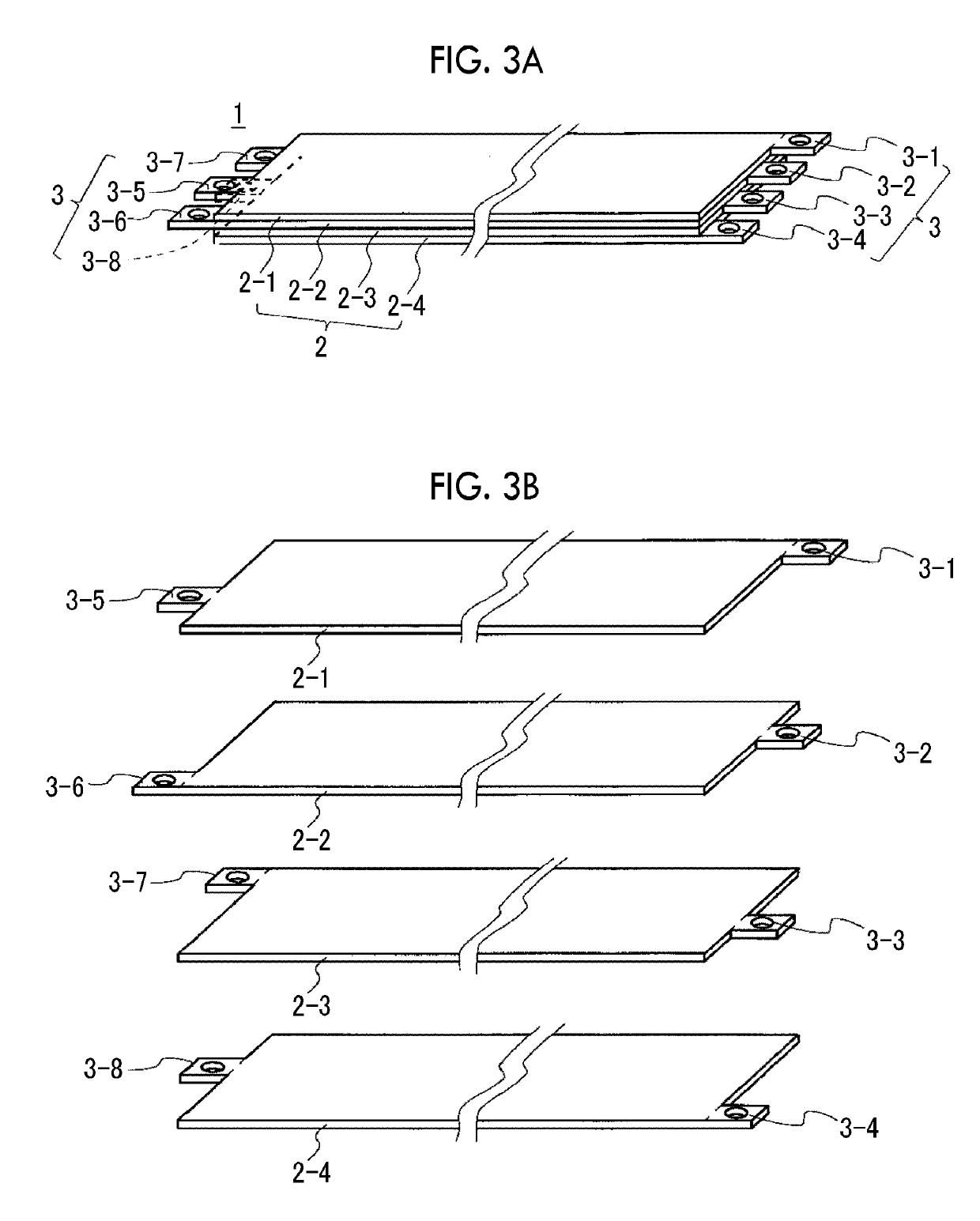
[0047]FIG. 3A shows a perspective view of a laminated flat electric wire 1 according to this embodiment. FIG. 3B shows an exploded perspective view of the laminated flat electric wire 1. FIG. 3C shows a plan view of the laminated flat electric wire 1 as viewed in the direction along the lamination direction. The laminated flat electric wire 1 includes four rectangular flat electric wires 2 (2-1 to 2-4), as an example. The respective flat electric wires 2 have insulating layers and are laminated in a state of being insulated from each other. The respective flat electric wires 2 include tabs 3 (3-1 to 3-4) extending from a first end portion in an extending direction. The respective flat electric wires 2 include tabs 3 (3-5 to 3-8) extending from a second end portion in the extending direction. Each of the tab...
example 1
OF BRANCH STRUCTURE
[0055]An example of a branch structure using the laminated flat electric wire 1 as described above and a branch box will be described. FIG. 5A shows an exploded perspective view of a branch box 51 according to a first example. FIG. 5B shows a plan view of a main section in a state where a plurality of laminated flat electric wires 1 is mounted on the branch box 51.
[0056]The branch box 51 has four bus bars 52 (52-1 to 52-4) corresponding to the respective flat electric wires 2 between a substrate 54 and a lid 55. The bus bars 52 have insulating layers and are laminated in a state of being insulated from each other. Each of the bus bars 52-1 to 52-4 has a shape in which tabs 53 (53-1 to 53-4) respectively extend from four sides configuring a rectangular shape. Each of the tabs 53 has a hole, as an example, and an insulating layer is not formed on the tab 53.
[0057]By preparing a plurality of laminated flat electric wires 1 and fixing the respective tabs 3-1 to 3-4 an...
example 2
OF BRANCH STRUCTURE
[0058]FIG. 6A shows an exploded perspective view of a main section of a branch box 151 according to a second example. FIG. 6B is a plan view showing a mounting direction of the laminated flat electric wires 1 on the branch box 151. FIG. 6C shows a perspective view of the main section in a state where the laminated flat electric wires 1 have been mounted on the branch box 151.
[0059]On a substrate 154 of the branch box 151, four bolts 152 (152-1 to 152-4) are provided perpendicularly to the substrate 154.
[0060]In the laminated flat electric wire 1, variation in electric resistance between the tabs 3 of the flat electric wire 2 is suppressed as described above, and therefore, even though the extension lengths of the tabs 3 are made different from each other, it is easy to keep variation in electric resistance within an allowable range. For this reason, in this example, the extension lengths of the tabs 3 are made different from each other within an allowable range, a...
PUM
 Abstract
Description
Claims
Application Information
 - R&D
- Intellectual Property
- Life Sciences
- Materials
- Tech Scout
- Unparalleled Data Quality
- Higher Quality Content
- 60% Fewer Hallucinations
Browse by: Latest US Patents, China's latest patents, Technical Efficacy Thesaurus, Application Domain, Technology Topic, Popular Technical Reports.
© 2025 PatSnap. All rights reserved.Legal|Privacy policy|Modern Slavery Act Transparency Statement|Sitemap|About US| Contact US: help@patsnap.com


