Grain dryer

a technology for drying grains and dryers, applied in the field of grain drying machines, can solve the problems of high grain cracking rate, poor quality of drying, and high need for air backpressure in these dryers

Active Publication Date: 2019-06-13
ING MEGA
View PDF0 Cites 19 Cited by
  • Summary
  • Abstract
  • Description
  • Claims
  • Application Information

AI Technical Summary

Benefits of technology

[0017]It is therefore an object of the present invention to provide a new grain dryer that makes it possible to significantly reduce energy consumption in order to provide a much faster process and a better grain quality.
[0018]It is also another object of the present invention to provide a grain dryer that has a grain preheating chamber that without removing moisture, allows a better drying process thereof.

Problems solved by technology

The grain that is against one of the faces of the corresponding column, tends to continue being “stuck” to that face while it descends, this is the reason why in these dryers there is provided a biasing device on all the column that causes the cereal on one side to move to the other, which is an undoubtedly unfavorable condition during the drying process, since the grain overheats in relation to the other that is next to the opposite face.
Consequently, the quality of the drying is very poor, causing a very high rate of “cracking” of the grain.
In addition, these dryers have floors inside to generate air deviations, which is a serious drawback because it favors the accumulation of “light components” that generate areas with a very high probability of fire sources, which is very frequent in dryers of columns of this type.
Likewise, the necessary air backpressure in these dryers is very high, because the air should pass through the perforations of the sheets, so they demand for their operation a large consumption of electrical energy.
Although these machines have been widely used and allow for large spaces for the entry of drying air between the columns that contain grain, in addition to the drawbacks mentioned above, it should be noted that they demand high costs for manufacturing multi-perforated sheets, inside of the columns they form very compact masses where the circulation of the drying air is hindered, and the surface contact of the drying air with the grain is not as efficient as would be expected, and they do not have the desired yield.
Unlike column dryers, these trestle dryers generate a good downward flow of grain but do not provide spaces or areas, also called plenums, for the passage of drying air.
Consequently, there is also in this case an almost compact mass of grain that hinders its drying.
These machines only provide a central area through which the air enters and, after passing through the trays and the grain, it goes out towards the periphery of the machine, so that the use of the thermal capacity of evaporation brought by hot air can not be efficiently used, because it also has to pass through an almost compact mass that descends only by a peripheral sector of the machine.
One of the most important deficiencies in this drying process is the “interference” effect that occurs between the deflectors and the volume of grain in the drying process.
The resulting grain of this process shows multiple superficial cracks, which is a sign of low quality, precisely, because it has been subjected to a constant heating, without the appropriate times for the progressive and controlled evaporation of the moisture contained therein.
Although the conventional dryers of the prior art have proved to work correctly in practice, there are still a number of drawbacks among which we can observe the high energy consumption involved in the dryers that exist today and that could not be solved so far.

Method used


Image

  • Grain dryer
  • Grain dryer
  • Grain dryer

Examples


Embodiment Construction

[0031]Referring now to the figures, it is seen that the invention consists in a new grain dryer that allows carrying out the drying process under ideal conditions of temperature-humidity, thus obtaining a better grain quality, and achieving a significant reduction in the energy consumption.

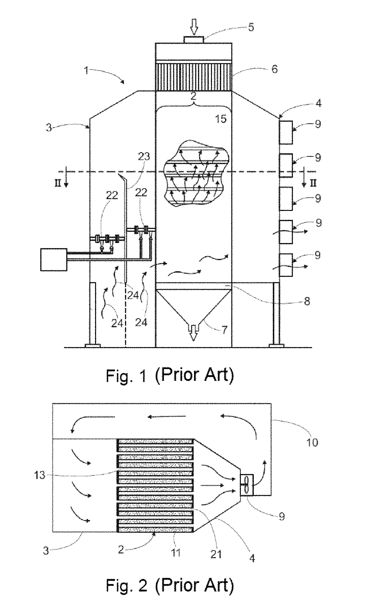
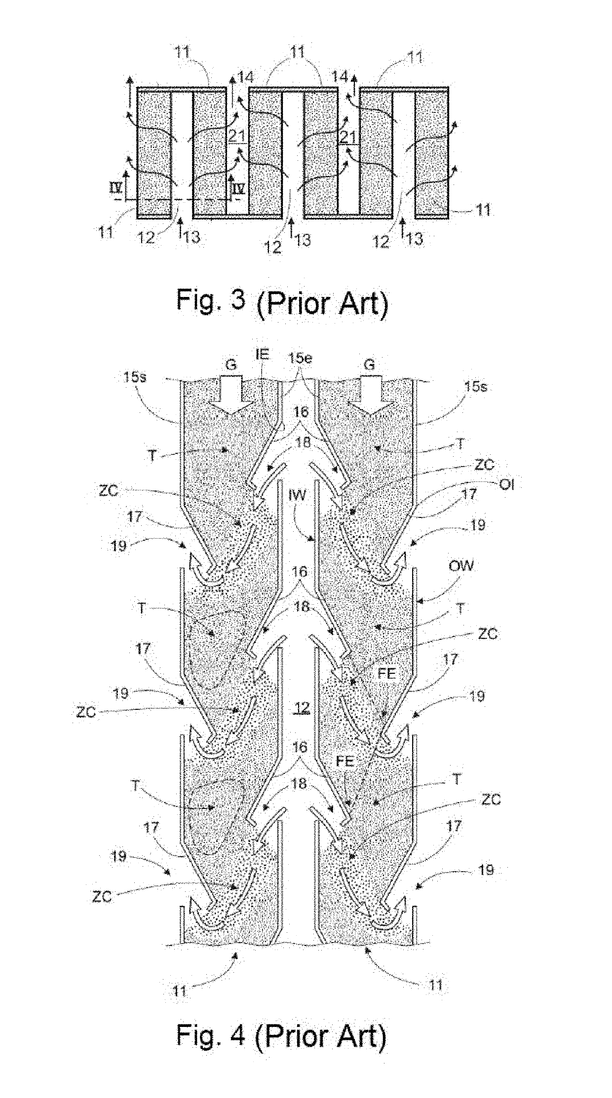
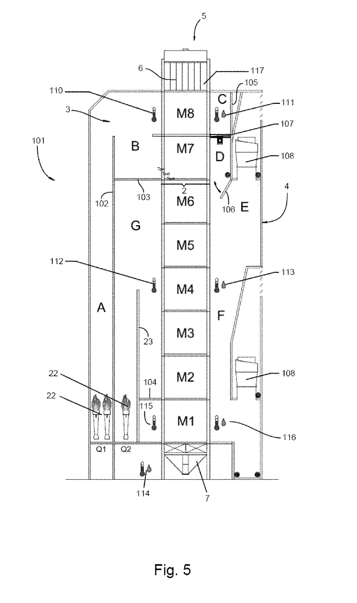
[0032]First and for merely exemplary purposes to provide a better understanding of the object of the present invention, reference will be made to the grain dryer of the Argentine Patent Application No. P20040104617 of INGENIERIA MEGA S.A. According to FIGS. 1 to 4 related to the prior art, it can be seen that INGENIERIA MEGA S.A.'s dryer comprises a vertical main structure 1, composed of a central body 2, through which the grain to be dried passes, a front chamber 3 for entering hot air and a rear chamber 4 for the exit of the air used. The main body 2 has in its upper part an inlet 5 from which wet grains are loaded, below which there is a loading hopper 6 that communicates with the central body ...


PUM


Abstract

Grain dryer of the type comprising a vertical main structure consisting of a central body through which the grain to be dried passes, a front hot air intake chamber and a rear used air outlet chamber, being that the main body has in its upper part an entrance from where wet grains are loaded, underneath which there is a loading hopper that communicates with the central body, wherein the grain descends along the central body within which it is dried during its fall by a flow of hot air that passes through the mass of grain, finally exiting through a discharge hopper arranged at the lower end of the dryer, the dryer of the invention being characterized in that it allows to significantly reduce the energy consumption in order to obtain a better quality of grain and a process much faster than conventional ones due to the arrangement of one or more preheating chambers without extraction of moisture from the grain.

Description

FIELD OF THE INVENTION[0001]The present invention relates to the field of agro-industry, and more particularly refers to a grain dryer that, unlike conventional dryers, allows performing the drying process of grains under ideal conditions of humidity and temperature, improving their quality and significantly reducing energy consumption. Even though in the present description reference is made to a grain dryer of the type formed by a column structure from whose upper end the grain volume to be dried is loaded, it should be clear that the invention can be adapted and used in different types and arrangements of grain dryers either independently or jointly with means, devices or related arrangement.DESCRIPTION OF THE PRIOR ART[0002]A great variety of grain dryers is known in the field of the art, which can be classified according to the structural features that they have for grain displacement path and for the circulation of the drying air thereof.[0003]Currently, among the existing dry...

Claims


Application Information

Patent Timeline
Patent Type & Authority Applications(United States)
IPC IPC(8): A23B9/08F26B25/22F26B25/06G05D22/02
CPCG01K1/045F26B25/002G01D21/02G01N27/121G05D22/02A23B9/08F26B25/22F26B25/06F26B2200/06F26B17/126F26B21/04F26B21/08F26B21/10F26B23/02F26B25/08
Inventor VALFIORANI, MARCELO NORBERTOLOMBARDO, MARCELO EDUARDO
Owner ING MEGA
Why Eureka
Try Eureka