
Micro Display Device and Display Integrated Circuit

a micro-display device and integrated circuit technology, applied in static indicating devices, instruments, optical elements, etc., can solve the problems of increasing the size of the chip, reducing the production yield of the micro-display device, and increasing the manufacturing cost, so as to reduce spatial constraints, reduce manufacturing costs, and reduce the size

Active Publication Date: 2019-06-13
LG DISPLAY CO LTD
View PDF6 Cites 6 Cited by
  • Summary
  • Abstract
  • Description
  • Claims
  • Application Information

AI Technical Summary

Benefits of technology

This patent is about a new micro display device and display integrated circuit that can be made at a low cost and in a small size. It also aims to reduce spatial constraints.

Problems solved by technology

Such a structure is suitable for a large display device, but is not suitable for a small display device.
Such demands for a large screen and high resolution result in an increase in the size of a chip, which lowers the production yield of a micro display device and increases the manufacturing cost thereof.

Method used


Image

  • Micro Display Device and Display Integrated Circuit
  • Micro Display Device and Display Integrated Circuit
  • Micro Display Device and Display Integrated Circuit

Examples


Embodiment Construction

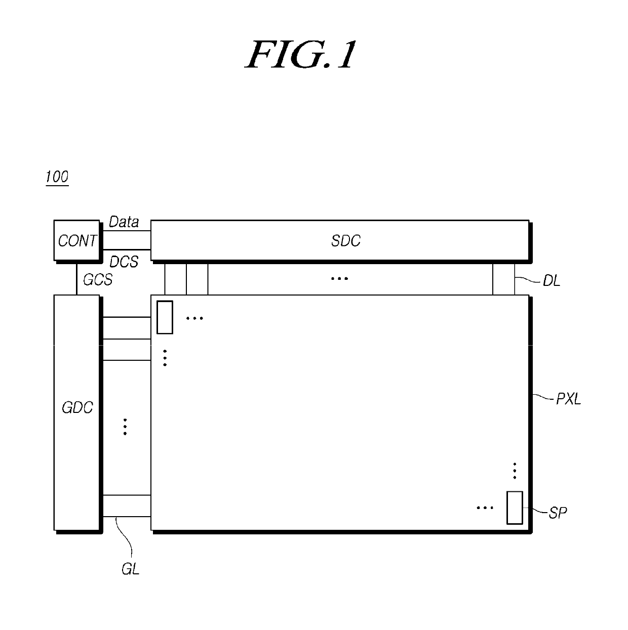
[0039]Hereinafter, some embodiments of the present disclosure will be described in detail with reference to the accompanying illustrative drawings. In designating elements of the drawings by reference numerals, the same elements will be designated by the same reference numerals although they are shown in different drawings. Further, in the following description of the present disclosure, a detailed description of known functions and configurations incorporated herein will be omitted when it may make the subject matter of the present disclosure rather unclear.

[0040]In addition, terms, such as first, second, A, B, (a), (b) or the like may be used herein when describing components of the present disclosure. Each of these terminologies is not used to define an essence, order or sequence of a corresponding component but used merely to distinguish the corresponding component from other component(s). In the case that it is described that a certain structural element “is connected to”, “is ...


PUM


Abstract

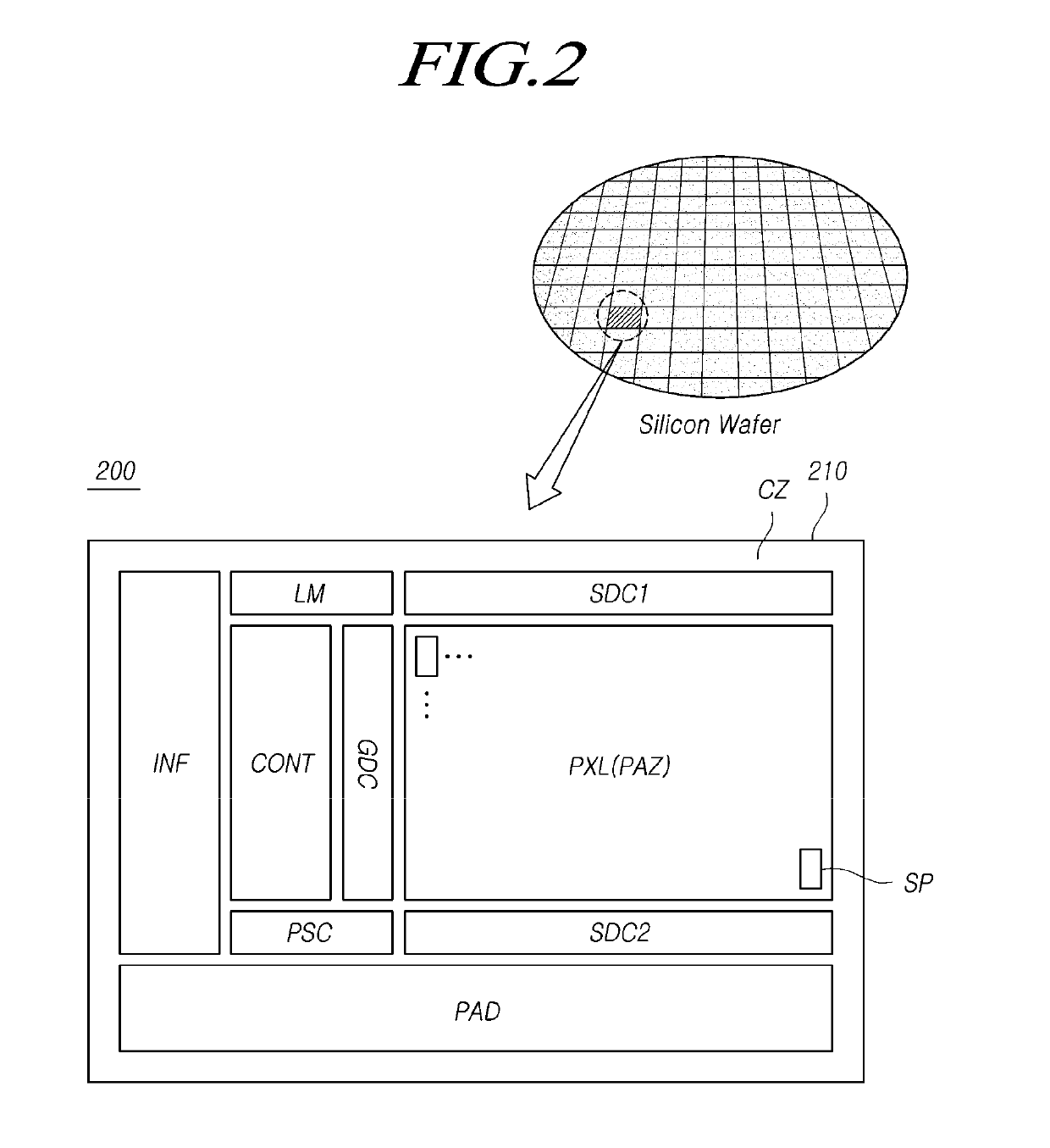
Embodiments of the present disclosure relate to a micro display device and a display integrated circuit and, more specifically, to a micro display device and a display integrated circuit, which include: a pixel array chip including a pixel array zone in which a plurality of subpixels defined by a plurality of gate lines and a plurality of data lines are arranged, and a through-zone in which a plurality of through-electrodes connected to the plurality of gate lines and the plurality of data lines in an outer area of the pixel array zone are arranged; and a driver chip including a circuit zone in which a driver circuit configured to drive the plurality of gate lines and the plurality of data lines through the plurality of through-electrodes is disposed, and thus have a high yield.

Description

CROSS REFERENCE TO RELATED APPLICATION[0001]This application claims priority to Republic of Korea Patent Application No. 10-2017-0169993, filed on Dec. 12, 2017, which is hereby incorporated by reference in its entirety.BACKGROUND1. Field of the Technology[0002]The present disclosure relates to a micro display device and a display integrated circuit.2. Description of the Prior Art[0003]A display device includes a display panel in which a plurality of subpixels are arranged and various driver circuits, such as a source driver circuit and a gate driver circuit, which drive the display panel.[0004]In a conventional display device, a display panel includes transistors, various electrodes, various signal lines, and the like, which are formed on a glass substrate. Driver circuits that can be implemented as an integrated circuit are mounted on a printed circuit and are electrically connected to the display panel through the printed circuit.[0005]Such a structure is suitable for a large dis...

Claims


Application Information

Patent Timeline
Patent Type & Authority Applications(United States)
IPC IPC(8): G09G3/3291G09G3/3266G09G3/3258H01L27/32G02B27/01H01L51/52
CPCG09G3/3291G09G3/3266G09G3/3258H01L27/322H01L27/3211H01L27/3276G02B27/0172H01L51/5234G09G2310/08G09G2300/0408G09G2300/0452G09G2300/0426G06F3/011G02B2027/0178G09G3/3233G09G2300/0842H10K59/131H10K59/80524G09G3/3225H01L27/156H10K59/127H10K59/35H10K50/828H10K59/38
Inventor PARK, HYUNKYUJUN, JAEHUN
Owner LG DISPLAY CO LTD
Learn More