Rotor bow management

a technology for rotor bows and engines, applied in the direction of engines, machines/engines, efficient propulsion technologies, etc., can solve the problems of engine rotors that bow or deform during cool-down, compressor blades rub, and high-pressure rotors are especially prone to this expansion, so as to reduce the incidence and/or severity of rotor bows and reduce the time

Active Publication Date: 2019-06-20
ROLLS ROYCE PLC
View PDF19 Cites 6 Cited by
  • Summary
  • Abstract
  • Description
  • Claims
  • Application Information

AI Technical Summary

Benefits of technology

[0016]using that stored pneumatic energy after the engine has been shut-down to rotate the high pressure rotor at a speed and for a duration that reduces rotor bow.
[0017]The method of the present disclosu

Problems solved by technology

The rotors are exposed to high temperatures in operation causing them to expand.
When the gas turbine engine is shut down, uneven cooling that occurs between the upper and lower half of the engine, for example due to heat rise, typically causes the engine rotors to bow or deform during cool-down.
The high pressure rotor is especially prone to this expansion.
If an engine is started while rotor bow is present, there is a risk that compressor blade rub will occur, damaging the engine.
Pilots, generally, and commercial airline operators, specifically, often need to be able to perform engine starts on the ground to strict time lines so it is highly undesirable to have to delay departure solely due to rotor bow or to risk engine wear or engine damage by starting the engine while there is residual rotor bowing.
Dry cranking means cranking the engine for several minutes at the dead crank speed by the starter motor but with the fuel shut off and the ignitors disabled.
This dry crank prior to start method however requires the engine to b

Method used


Image

  • Rotor bow management
  • Rotor bow management
  • Rotor bow management

Examples


Embodiment Construction

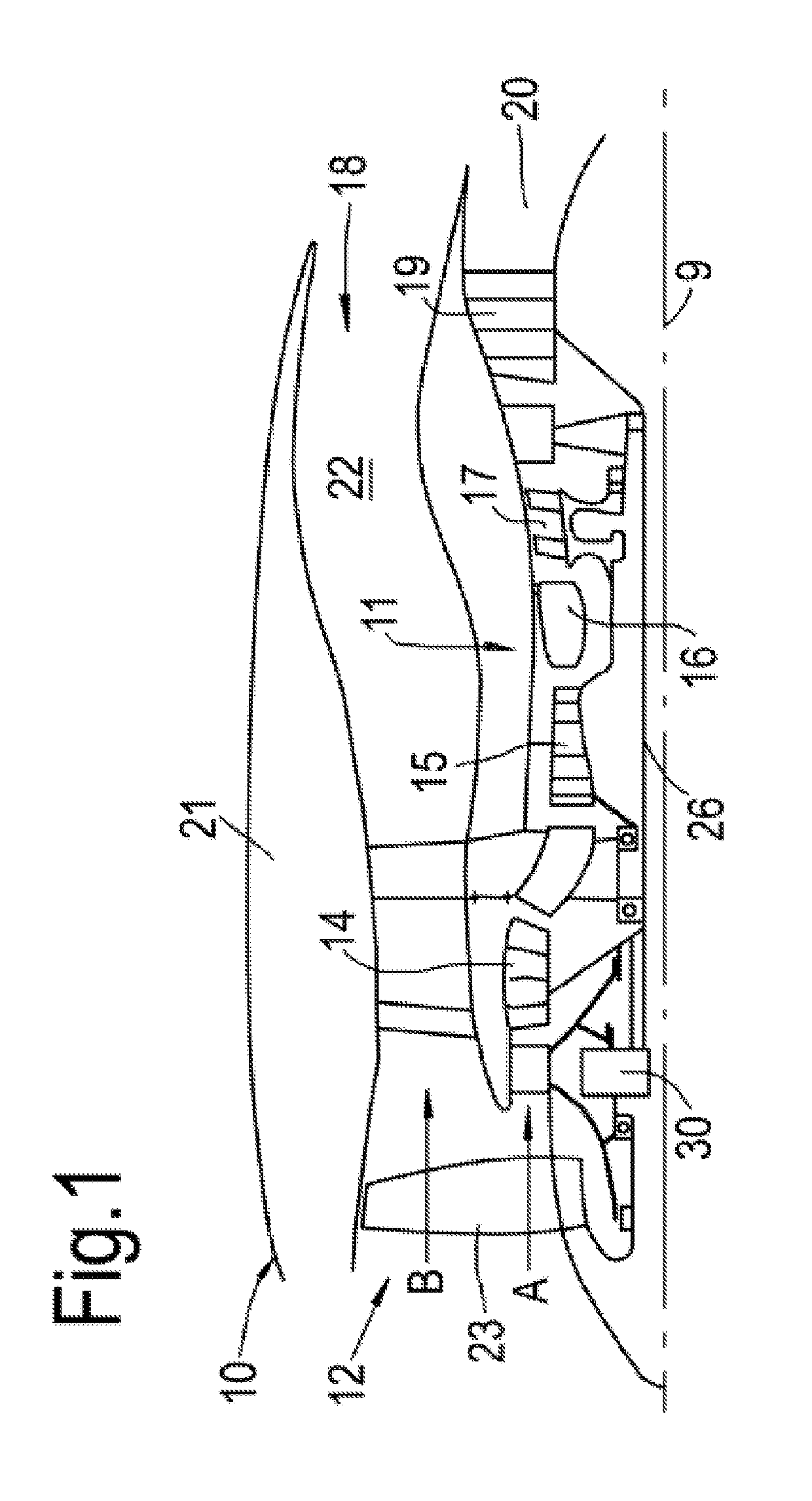
[0042]The present disclosure concerns a method of reducing rotor bow in a gas turbine engine, a pneumatic system for controlling rotor bow in the rotor of a gas turbine engine and a gas turbine engine that comprises that pneumatic system.

[0043]As mentioned above, when a gas turbine engine is shut down, it will experience a condition known as rotor bow whereby the engine rotors or shafts experience the effects of a thermal gradient that develops across the upper and lower part of the engine. The natural convection process during cooling results in the lower part of the engine cooling more quickly than the upper part. The engine rotors therefore experience this temperature differential that typically results in a slight bowing of one or more of the rotors, typically the system of rotors, providing the principal and rotational axis of the engine. Rotor bow typically affects the high pressure rotor in particular.

[0044]In some cases the degree of deformation of the rotor or system of rot...


PUM


Abstract

A method of reducing rotor bow in a high pressure rotor of a gas turbine engine that has in axial flow a low pressure rotor and a high pressure rotor. The method involves storing bleed air from the gas turbine engine when the engine is running to provide stored pneumatic energy; and using that stored pneumatic energy after the engine has been shut-down to rotate the high pressure rotor at a speed and for a duration that reduces rotor bow. A gas turbine engine wherein rotor bow in the high pressure rotor after engine shut-down has been reduced by carrying out the aforesaid method is also disclosed.

Description

CROSS-REFERENCE TO RELATED APPLICATIONS[0001]This specification is based upon and claims the benefit of priority from United Kingdom patent application GB 1720944.6 filed on Dec. 15, 2017, the entire contents of which are incorporated herein by reference.BACKGROUNDTechnical Field[0002]The present disclosure concerns gas turbine engines and their manufacture. More specifically, the present disclosure concerns a method of managing rotor bow in gas turbine engines, for example civil aero gas turbine engines.Description of the Related Art[0003]Gas turbine engines typically have in axial flow a low pressure rotor and a high pressure rotor. Some engines have an intermediate pressure rotor between the low pressure rotor and the high pressure rotor. The rotors are exposed to high temperatures in operation causing them to expand. The high pressure rotor is typically exposed to highest of these temperatures.[0004]When the gas turbine engine is shut down, uneven cooling that occurs between the...

Claims


Application Information

Patent Timeline
IPC IPC(8): F02C6/08F02C1/02F01D21/06F01D19/00
CPCF02C6/08F02C1/02F01D21/06F01D19/00F02C9/18F05D2270/305F05D2260/606F05D2260/42F01D19/02F01D5/147F02C7/268F01D25/34F01D25/36F02C6/16F02C7/277F02C7/32F05D2270/65Y02E60/16Y02T50/60
Inventor STEVENSON, ANDREW
Owner ROLLS ROYCE PLC
Why Eureka
Try Eureka