Near-field pulse detection

Active Publication Date: 2019-06-20
LEICA GEOSYSTEMS AG
View PDF0 Cites 1 Cited by
  • Summary
  • Abstract
  • Description
  • Claims
  • Application Information

AI Technical Summary

Benefits of technology

The invention relates to an airborne range finder that can be used on an aircraft to surveying a target. The range finder comprises an emitter that emits electromagnetic pulses towards the target, a receiver that receives backscattered pulses, and a detector that detects and stores pulses. The detector has a projection surface with an inner area and an outer area, and pulses are imaged onto the inner area with a focusing optics and onto the outer area with a wider focusing optics. The detector also has a detector that detects pulses within the outer area and tags them with a corresponding time. The control unit controls the emitter and the receiver. The range finder can detect pulses from a distance equal to or longer than a threshold distance and from objects closer than the threshold distance. The detector can also suppress the outputting of pulses on the outer area of the projection surface. The range finder can also have an optical dissection element and a positioning sensor to determine flight altitude and position data.

Problems solved by technology

Occasionally, before arriving at the target outgoing pulses may hit obstacles, such as particles or clouds, potentially causing false measurements because the times of flight calculated with these reflected pulses do not represent a distance to the intended target.
While false measurement values could be sorted out based on the intensity of the received pulses, this method is ineffective when the intensity of the light backscattered from the near-field obstacle—e.g. due to fractional backscattering—is similar to the intensity of a signal regularly reflected from the target.
However, this solution becomes impractical, too, when the laser range finder operates in Multiple Pulses in the Air (MPiA) mode.
This is where close range returns confuse the sequences: they happen to be falsely considered as target returns because they cannot easily be discriminated from the true target returns.
The likelihood of these near-field reflections being similar in size and shape compared to true target reflections is quite high, making it very hard to filter them out.

Method used


Image

  • Near-field pulse detection
  • Near-field pulse detection
  • Near-field pulse detection

Examples


Embodiment Construction

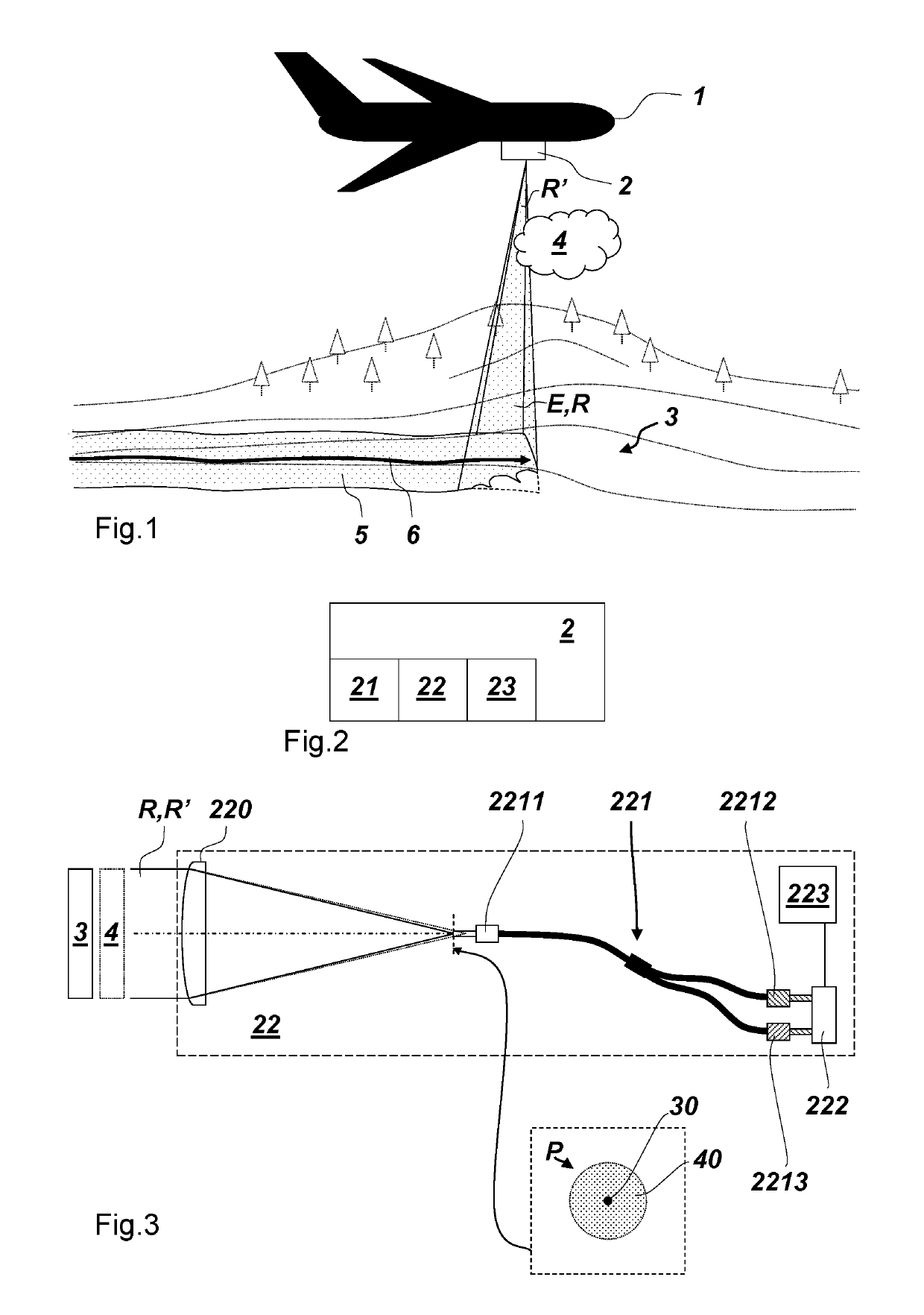
[0032]FIG. 1 shows an aircraft 1 flying over a ground surface 3, which is the intended target, following a flight path 6 (trajectory). The aircraft carries an airborne range finder 2 according to an embodiment of the invention. By emitting multiple light pulses E and receiving them as backscattered pulses R, the range finder can at least continuously measure the flight altitude, but in particular record a two-dimensional (2D) profile of the flight path 6. In a further particular case, the range finder can rotate or oscillate the pulse path, and therewith sample a plurality of points 5 of the swath of the aircraft. In real-time or afterwards in a post processing, a point cloud can be generated based on the laser pulses E,R emitted and received by the range finder, which are registered with according time stamps of their emission / reception.

[0033]The cloud 4 represents an exemplary near-field obstacle potentially causing the range finder 2 to generate false measurement values which do ...


PUM


Abstract

A airborne range finder arranged on an aircraft for surveying a target, the finder comprising an emitter configured for emitting electromagnetic pulses towards the target, a receiver for receiving backscattered pulses, wherein the receiver comprises a projection surface comprising an inner area and an outer area, focusing optics configured for imaging pulses backscattered from a distance equal to or longer than a threshold distance onto the inner area, and pulses backscattered from a distance shorter than said threshold distance onto the inner area and a part of the outer area, a detector configured for detecting and outputting pulses imaged onto the projection surface, and a recorder configured for reading the detector and storing pulses detected only within the inner area as target pulses, storing pulses detected within the outer area as near-field pulses, and tagging each stored pulse with a corresponding pulse reception time, and a control unit.

Description

CROSS-REFERENCE TO RELATED APPLICATIONS[0001]This application claims priority to European Patent Application No. 17209172, filed on Dec. 20, 2017. The foregoing patent application are incorporated herein by reference.FIELD OF INVENTION[0002]The present invention relates to an airborne range finder configured to be arranged on an aircraft for surveying a target.BACKGROUND[0003]Surveying a 2D or 3D topography of a target with an airborne surveying device is commonly achieved by laser range finders which send out pulses of light to sample the target, such as the ground surface, and receive the pulses after they reflected from the target. The time of flight between the emission and the return of each pulse can be used to determine according distances to target.[0004]Occasionally, before arriving at the target outgoing pulses may hit obstacles, such as particles or clouds, potentially causing false measurements because the times of flight calculated with these reflected pulses do not rep...

Claims


Application Information

Patent Timeline
IPC IPC(8): G01S17/10G01S17/42G01S17/02G01S17/93G01S17/26G01S17/86G01S17/89G01S17/933
CPCG01S17/102G01S17/933G01S17/023G01S17/42G01S17/10G01S17/89G01S7/4816G01S7/4876G01C15/002G01C3/08G01S17/26G01S17/86
Inventor YANG, QUAN
Owner LEICA GEOSYSTEMS AG
Why Eureka
Try Eureka