
Rail-guided trolley system, and rail-guided trolley

a trolley system and trolley technology, applied in the direction of elevated railways, conveying, transportation and packaging, etc., can solve the problems of not only vibration being applied to the article, but limited position for loading or unloading the article, and preventing vibration or an impact. , the orientation of the traveling wheel is able to be changed easily, and the effect of preventing vibration or an impa

Active Publication Date: 2019-06-20
MURATA MASCH LTD
View PDF0 Cites 3 Cited by
  • Summary
  • Abstract
  • Description
  • Claims
  • Application Information

AI Technical Summary

Benefits of technology

The present invention provides rail-guided trolley systems and trolleys that can prevent the traveling wheel from falling into a rail gap, prevent vibration or impact from being applied to an article, and easily change the orientation of the traveling wheel. The main body of the trolley system can fit within a cell of the grid pattern of the rails, ensuring high-density transportation using a large number of trolleys. The auxiliary wheel prevents the traveling wheel from falling into a rail gap, and prevents vibration or impact from being applied to an article. The orientation of the traveling wheel can be easily changed. The auxiliary wheel reduces unnecessary contact with the rail, and the rotation radius of the traveling wheel and the auxiliary wheel is small, making the space required for changing the traveling direction small. The auxiliary wheel has a smaller friction coefficient with respect to the rails, ensuring smooth rotation. Overall, the invention provides safer and efficient transportation using a rail-guided trolleyl system.

Problems solved by technology

Therefore, when loading or unloading an article from or to a predetermined position below the rails, it is necessary to raise or lower the article using a location where there is no rail, or a space between the rails, and as a result, the position for loading or unloading the article is limited.
If there is a gap in a part of a rail as described above, there is a possibility that the traveling wheel may fall into the gap while the trolley is traveling and this may result in vibration being given to the article.
Moreover, when changing the orientation of the traveling wheel at an intersecting portion of the rail, there is a possibility that not only may vibration be applied to the article but the orientation of the traveling wheel may also not be changed easily, as a result of the traveling wheel being caught on the gap.

Method used


Image

  • Rail-guided trolley system, and rail-guided trolley
  • Rail-guided trolley system, and rail-guided trolley
  • Rail-guided trolley system, and rail-guided trolley

Examples


Embodiment Construction

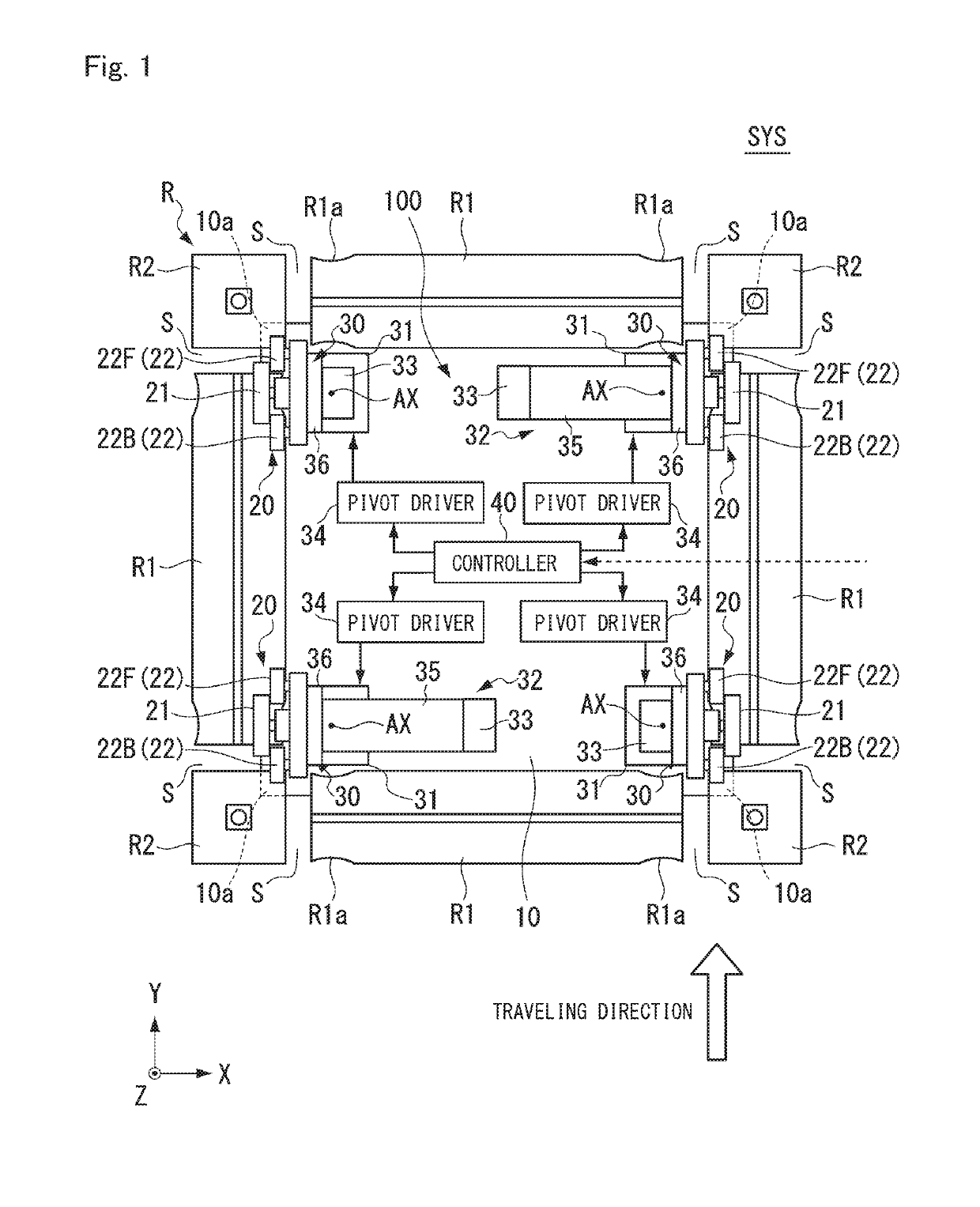
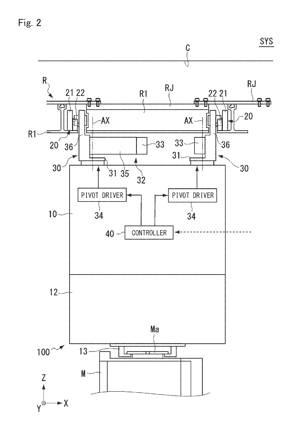
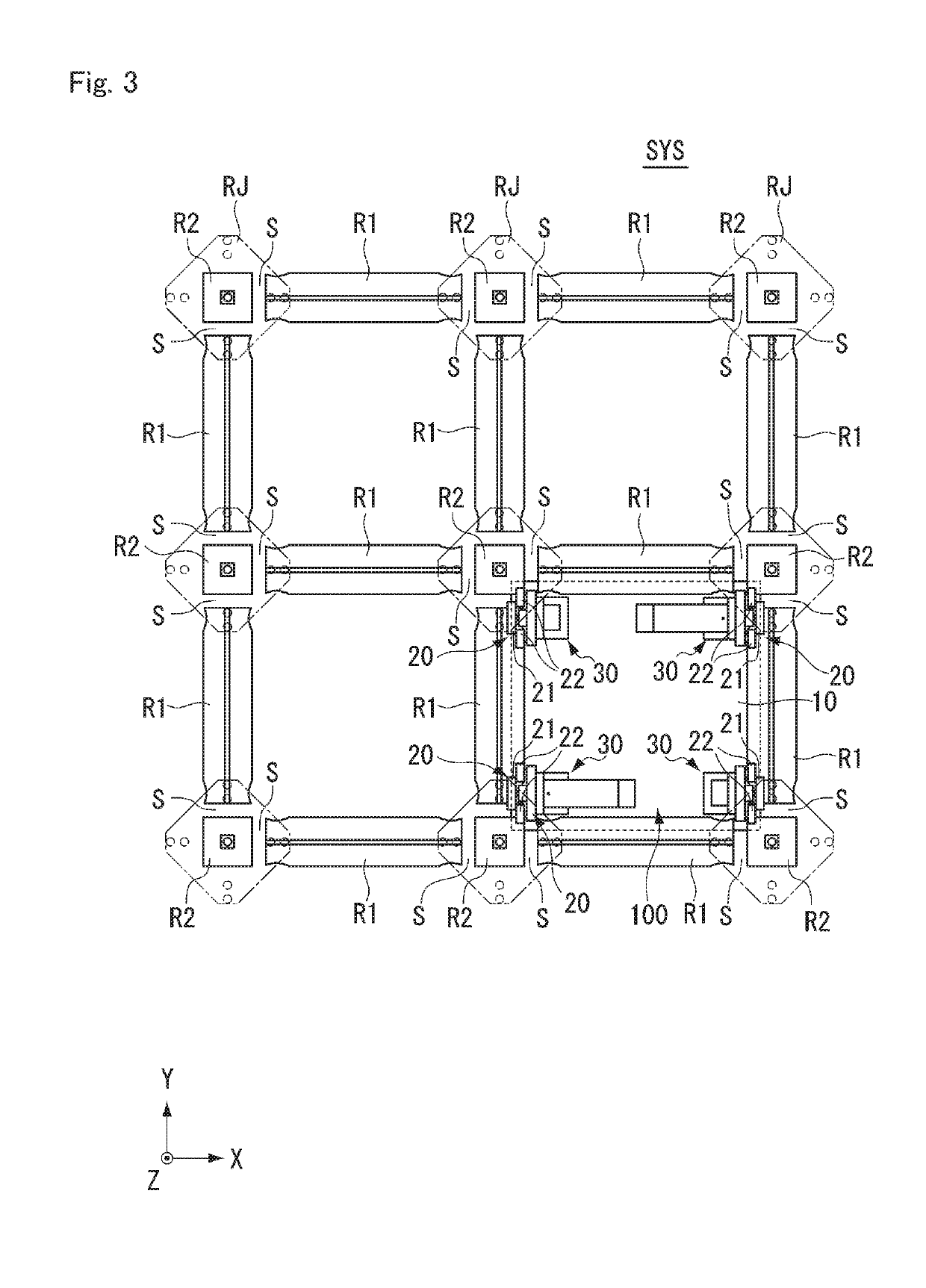
[0024]The following describes preferred embodiments of the present invention with reference to the drawings. However, the present invention is not limited to the preferred embodiments. Note that, in the drawings, scale is changed as necessary to illustrate the preferred embodiments, such as by enlarging or by emphasizing an element or structure. In the following drawings, an XYZ coordinate system is used to describe the directions in each drawing. In the XYZ coordinate system, a plane that is parallel to a horizontal plane is defined as an XY plane. In this XY plane, one linear direction which is a traveling direction of the rail-guided trolley 100 is denoted as a Y direction for convenience and a direction orthogonal to the Y direction is denoted as an X direction. A direction perpendicular to the XY plane is denoted as a Z direction. For each of the X direction, the Y direction, and the Z direction, description is made with a definition in which a direction indicated by an arrow i...


PUM


Abstract

A rail-guided trolley system includes a main body that, along rails at least partially in a grid pattern, holds and transports a transportation container on a lower side of the rails, traveling wheels at each of four corners of the main body and that travel on the rails, a controller that controls pivot drivers that change orientations of the traveling wheels, and auxiliary wheels each located at least in either front or rear in a traveling direction of the traveling wheel.

Description

BACKGROUND OF THE INVENTION1. Field of the Invention[0001]The present invention relates to a rail-guided trolley system, and a rail-guided trolley.2. Description of the Related Art[0002]In manufacturing factories such as semiconductor manufacturing factories, for example, articles such as transportation containers (FOUPs, reticle pods) for containing semiconductor wafers or reticles are transported by a rail-guided trolley. As a system that includes this rail-guided trolley, there is known a system in which a trolley that holds an article travels along rails installed on a ceiling (for example, see Japanese Unexamined Patent Application, First Publication No. 2012-111635), and in order to diversify traveling paths for a trolley, there has been proposed a configuration in which rails are arranged in a grid pattern to allow a trolley to travel in horizontal and vertical directions (for example, see Japanese Patent Application No. 2016-041532).[0003]In the above rail-guided trolley sys...

Claims


Application Information

Patent Timeline
Patent Type & Authority Applications(United States)
IPC IPC(8): H01L21/677B65G47/90B65G1/04
CPCH01L21/67724B65G47/90B65G1/0457H01L21/6773H01L21/67733B61B3/02B65G1/00B65G1/04H01L21/67706B65G2201/0297
Inventor ITO, YASUHISA
Owner MURATA MASCH LTD
Learn More