Vehicle monitoring system using a plurality of cameras

Active Publication Date: 2019-07-04
KOITO MFG CO LTD
View PDF7 Cites 17 Cited by
  • Summary
  • Abstract
  • Description
  • Claims
  • Application Information

AI Technical Summary

Benefits of technology

The vehicle monitoring systems described in this patent allow for multiple areas around a vehicle to be monitored using multiple vehicle lamps. Additionally, the system avoids protruding cameras and ensures redundant monitoring in case of failure. The separate processing of videos by separate electronic control units (ECUs) also reduces the time from shooting to display.

Problems solved by technology

However, if the cameras are mounted on locations similar to door mirrors, the amounts of protrusion from the vehicle body are increased so as to preclude exploitation of the full potential of the use of cameras.
Moreover, as these cameras are electronic equipment and also connected to multiple electrical components, they have higher failure rates compared to mechanical door mirrors.
If a camera fails, a view of the rear side of the vehicle can no longer be obtained, thus reducing the safety.

Method used


Image

  • Vehicle monitoring system using a plurality of cameras
  • Vehicle monitoring system using a plurality of cameras
  • Vehicle monitoring system using a plurality of cameras

Examples


embodiment 1

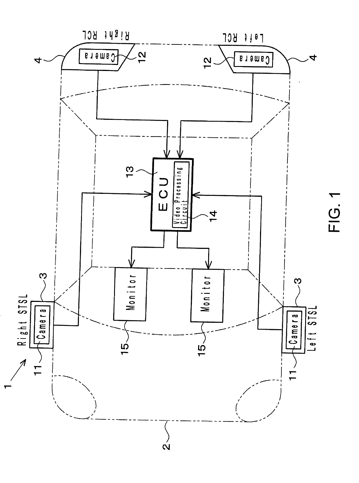
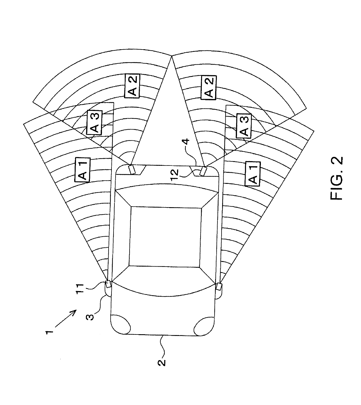
[0070]In a vehicle monitoring system 1 of the first embodiment shown in FIGS. 1 and 2, first cameras 11 are contained in right and left STSLs 3, and second cameras 12 are contained in right and left RCLs 4. The STSLs 3 are provided on both right and left side surfaces of a vehicle body 2, and the first cameras 11 shoot first areas A1 at the rear sides of the vehicle. The RCLs 4 are provided on the rear surface of the vehicle body 2, and the second cameras 12 shoot second areas that are more inward in the width direction of the vehicle than the first areas A1.

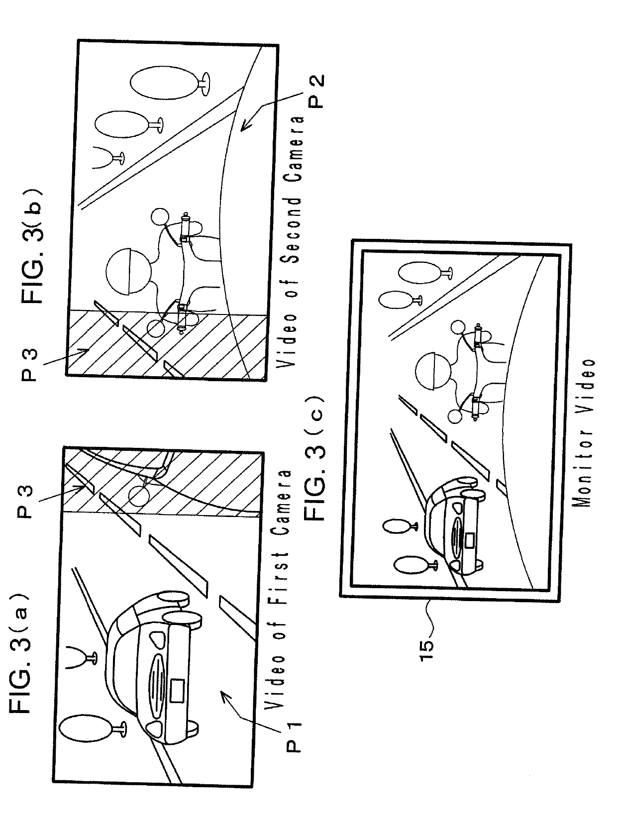
[0071]The videos shot by the first cameras 11 and the second cameras 12 are transmitted from these cameras 11 and 12 to an electronic control unit (ECU) 13. The ECU 13 is installed in an appropriate location in the vehicle and includes a video processing circuit 14 to combine the videos from the cameras 11 and 12. Also, a pair of monitors 15 is installed to the right and left of the driver's seat to display the videos combined b...

embodiment 2

[0075]In a vehicle monitoring system 1 of a second embodiment shown in FIGS. 5, 6, and 7, first cameras 11 are contained in right and left STSLs 3, and a second camera 12 is contained in an HMSL 5. The HMSL 5 shown in FIG. 6 is installed on the cabin side of the rear window 7 at an elevated location in the vehicle body, and the second camera 12 shoots the rear of the vehicle through the rear window 7. A window cleaner 8 is installed above the HMSL 5 to clean the rear window 7 as well as the view of the second camera 12 using cleaning fluid squirted from a cleaner nozzle 9. Therefore, the second embodiment has the advantages of being able to clearly shoot a wide range of area behind the vehicle (see FIG. 7) with the single second camera 12 installed in the HMSL 5 and of being able to inexpensively configure the entire monitoring system 1 using three cameras.

embodiment 3

[0076]In a vehicle monitoring system 1 of a third embodiment shown in FIG. 8, first cameras 11 are contained in right and left RCLs 4, and a second camera 12 is contained in an HMSL 5. Additionally, the first cameras 11, which are located more outward in the width direction of the vehicle than the second camera 12, are adapted to shoot the first areas (the areas indicated by A2 in FIG. 2) at the rear sides of the vehicle, and the second camera 12, which is located more inward in the width direction of the vehicle than the first cameras 11, is adapted to shoot the second area (the area indicated by A2 in FIG. 7) at the rear of the vehicle. According to the third embodiment, as the first cameras 11 are contained in the RCLs 4, it is possible to eliminate protrusions from the side surfaces of the vehicle.


PUM


Abstract

Problem: To provide a vehicle monitoring system capable of checking a wide range of area at the rear of a vehicle to afford a high level of safety, without increasing an amount of protrusion from the side surface of the vehicle body.Solution: A vehicle monitoring system 1 is provided with a first camera 11 that shoots a first area at the rear side of a vehicle; a second camera 12 that shoots a second area further toward the inside in the width direction of the vehicle compared with the first area; an ECU 13 that combines videos captured by the two cameras; and a monitor 15 that displays the combined image. The first camera 11 is contained in an STSL 3 on a vehicle body side surface, and the second camera 12 is installed in an RCL 4 or a high mounted stop lamp at the rear of the vehicle body. A video processing circuit 14 performs correction to improve the visibility of the videos of an overlapping section captured by the cameras 11 and 12. The first camera 11 may be equipped with a wide-angle lens having a field of view angle greater than 90°.

Description

TECHNICAL FIELD[0001]The present invention relates to a vehicle monitoring system that gathers scene information about the surroundings of a vehicle with a plurality of cameras or sensors and displays the information on monitors.BACKGROUND ART[0002]In recent years, technologies have been developed that use a camera monitoring system (CMS) in place of door mirrors. By checking the rear through images shot by the cameras, it is possible to downsize the system, enhance the fuel-efficiency and safety, and reduce the wind noise in comparison to door mirrors. However, if the cameras are mounted on locations similar to door mirrors, the amounts of protrusion from the vehicle body are increased so as to preclude exploitation of the full potential of the use of cameras.[0003]In view of the above, conventionally, a technology has been proposed to contain a camera in the housing of a side-turn signal lamp (STSL). For example, Patent Literature 1 describes “a vehicular periphery imaging device”...

Claims


Application Information

Patent Timeline
IPC IPC(8): B60R1/00B60R11/04B60S1/56G06K9/00H04N7/18
CPCB60R1/00B60R11/04B60S1/56G06K9/00791H04N7/181B60R2300/105B60R2300/802B60R2300/303B60R1/06F21V33/00H04N7/18B60R1/26G06V20/56
Inventor TATARA, NAOKIOKAMURA, TOSHIHIRO
Owner KOITO MFG CO LTD
Why Eureka
Try Eureka