Method for transferring a useful layer into a supporting substrate

a useful layer and supporting substrate technology, applied in the direction of coatings, microstructural devices, microstructured technology, etc., can solve the problems of failure of the useful layer transfer to the carrier substrate, the prior-art process is not entirely satisfactory, etc., to reduce the risk of crack propagation during step c) and inhibit the blistering of the implanted species

Active Publication Date: 2019-07-04
COMMISSARIAT A LENERGIE ATOMIQUE ET AUX ENERGIES ALTERNATIVES
View PDF0 Cites 7 Cited by
  • Summary
  • Abstract
  • Description
  • Claims
  • Application Information

AI Technical Summary

Benefits of technology

[0023]Thus, such a process according to the invention allows, by virtue of the presence of such an amorphous zone, the limits on the maximum width of the cavity beyond which a failure of the useful layer transferred to the carrier substrate is observed to be pushed back. Specifically, such an amorphous zone allows the blistering of the implanted species, which is caused by the gas resulting from the recombination of said species, to be inhibited locally. In addition, this inhibition of the blistering of the implanted species allows a thin useful layer to be transferred, without fear of mechanical failure or even breakage thereof. The inhibition of the blistering of the implanted species is enhanced when the amorphous zone is located completely facing the cavity at the end of step b).
[0024]Furthermore, such an amorphous zone has a lower Young's modulus than a single-crystal structure (for example of about 20% lower for amorphous silicon with respect to single-crystal silicon), this allowing the risks of propagation of a crack during step c) to be decreased.
[0050]Thus, one procured advantage is to be able to easily obtain a “buried” amorphous zone, i.e. an amorphous zone located away from the first surface of the donor substrate, this not being conceivable with a deposition technique.
[0052]Thus, one advantage procured by such a buried amorphous zone, i.e. an amorphous zone that is closer to the weakened zone, is an improvement in the effectiveness of the inhibition of the blistering of the implanted species caused by the gas resulting from the recombination of said species. Furthermore, where appropriate, such a buried amorphous zone allows the quality of the recrystallization in step d) to be improved. Lastly, another advantage procured by such a buried amorphous zone is that it may be easily removed by sacrificial oxidation or thinning.
[0054]Thus, one procured advantage is to improve the effectiveness of the inhibition of the blistering of the implanted species.
[0057]Thus, one advantage procured by such a periodic array is the ability to obtain an excellent inhibition of the blistering of the implanted species without requiring an amorphous zone to lie completely facing the cavity at the end of step b)—which would require an alignment, which may be tricky to achieve.

Problems solved by technology

However, such a prior-art process is not entirely satisfactory in so far as D1 teaches that the thickness of the useful layer, denoted t, defines a maximum theoretical width of the cavity, denoted Wlim, that is proportional to t2.
In other words, for a given thickness t of the useful layer, a width of the cavity larger than Wlim will lead to a failure of the useful layer transferred to the carrier substrate, which is related to blistering of the species implanted in the cavity.

Method used


Image

  • Method for transferring a useful layer into a supporting substrate
  • Method for transferring a useful layer into a supporting substrate
  • Method for transferring a useful layer into a supporting substrate

Examples


Embodiment Construction

[0075]Elements that are identical or that perform the same function in the various embodiments have been given the same references, for the sake of simplicity.

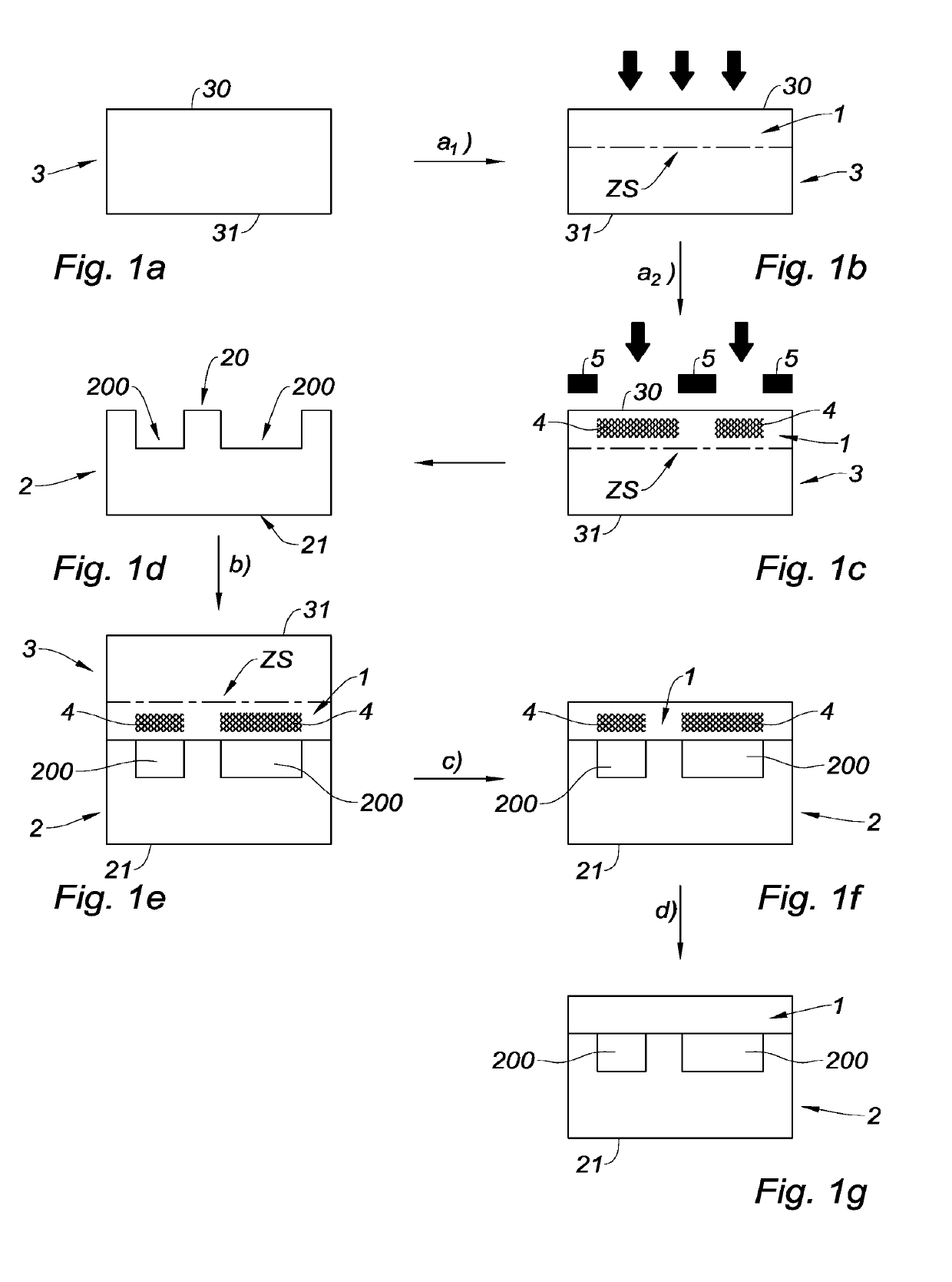
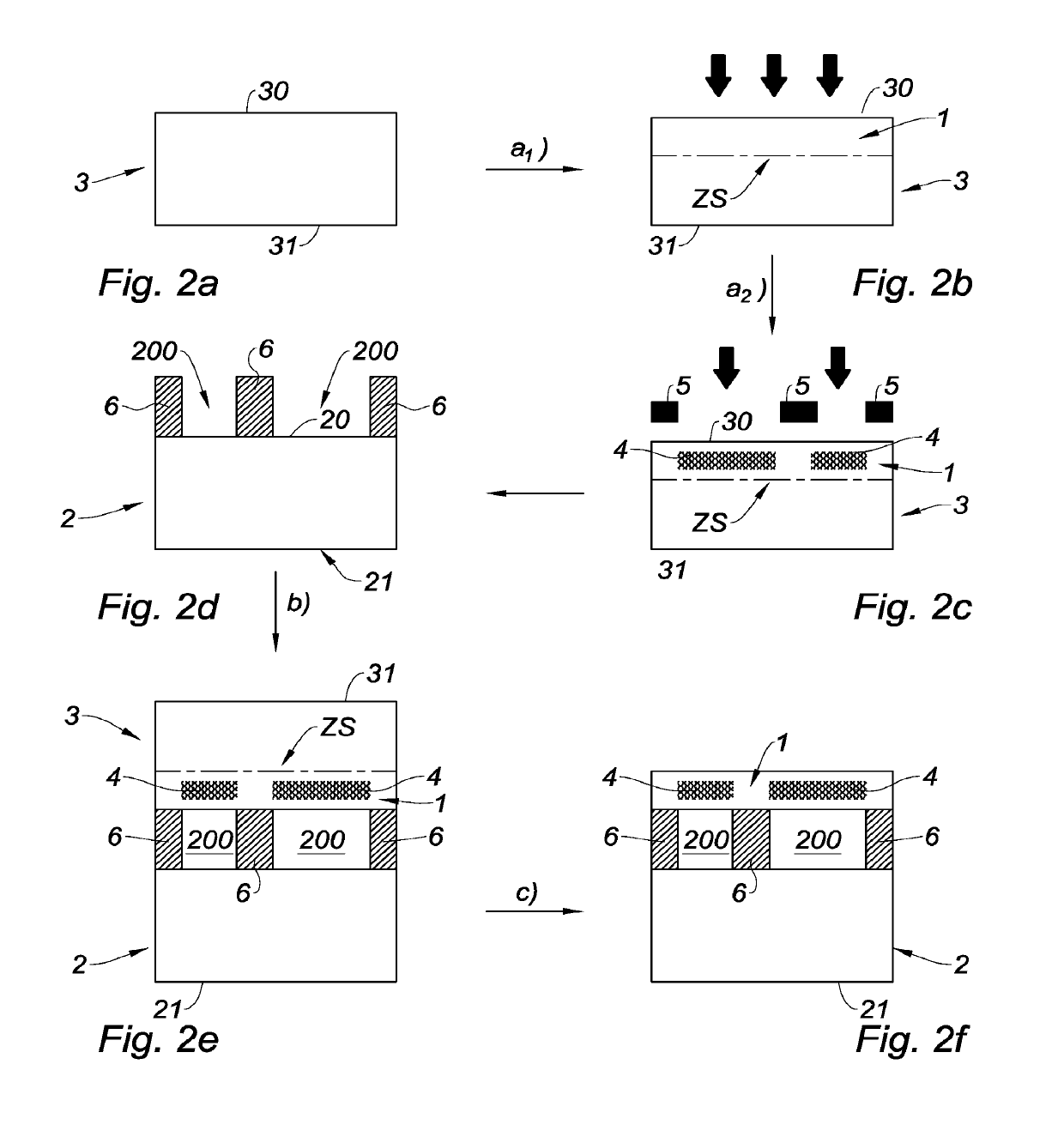
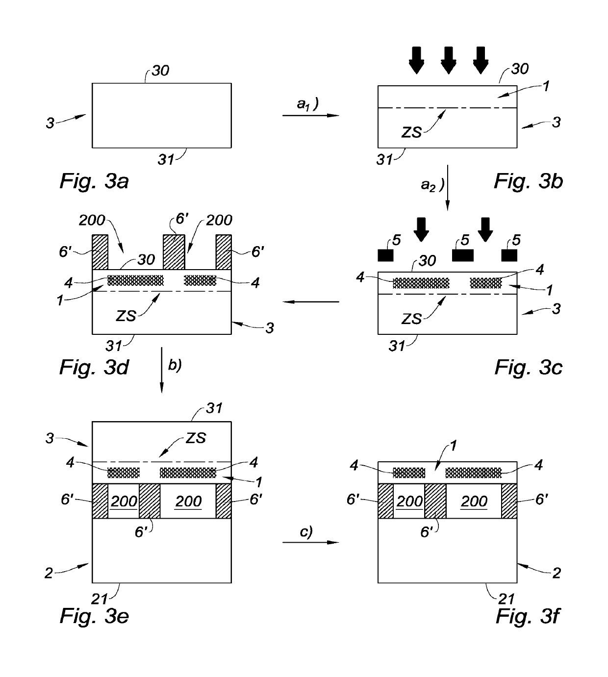
[0076]One subject of the invention is a process for transferring a useful layer 1 to a carrier substrate 2 including a first surface 20, the process including the successive steps of:[0077]a) providing a donor substrate 3 including:[0078]a first surface 30,[0079]a weakened zone ZS comprising implanted species,[0080]the useful layer 1, which is bounded by the weakened zone ZS and by the first surface 30 of the donor substrate 3,[0081]an amorphous zone 4 lying, in the useful layer 1, parallel to the weakened zone ZS;[0082]b) assembling, on the side of the first surface 30 of the donor substrate 3 and on the side of the first surface 20 of the carrier substrate 2, the donor substrate 3 with the carrier substrate 2 by bonding; step b) being executed so that the amorphous zone 4 is at least partially facing at least one cavity 200 ...


PUM

PropertyMeasurementUnit
electrical conductivityaaaaaaaaaa
energyaaaaaaaaaa

Abstract

A process for transferring a useful layer to a carrier substrate including a first surface is provided, the process including the steps of: providing a donor substrate including a first surface, a weakened zone including implanted species, the useful layer, which is bounded by the weakened zone and by the first surface of the donor substrate, and an amorphous zone disposed, in the useful layer, parallel to the weakened zone; assembling, on a side of the first surface of the donor substrate and on a side of the first surface of the carrier substrate, the donor substrate with the carrier substrate by bonding, such that the amorphous zone is at least partially facing at least one cavity that is partially bounded by the first surface of the donor substrate; and splitting the donor substrate along the weakened zone so as to reveal the useful layer.

Description

TECHNICAL FIELD[0001]The invention relates to the technical field of the transfer of a useful layer, belonging to a donor substrate, to a carrier substrate. The donor substrate and / or the carrier substrate is provided with at least one surface cavity.[0002]The invention is in particular applicable to the fabrication of a membrane over the cavity, such as used for micromechanical systems (MEMS), for example in a pressure sensor, a resonator, a microphone or even a biochemical sensor. The transferred useful layer may also be used as a protective cover, for example for a component, or even as a hermetic encapsulating means.PRIOR ART[0003]One process known in the prior art, in particular from document C.-H. Yun et al., “Fabrication of Silicon and Oxide Membranes Over Cavities Using Ion-Cut Layer Transfer”, Journal of Microelectromechanical Systems, vol. 9, no. 4, 474-477, 2000 (D1 below), is a process for transferring a useful layer to a carrier substrate, the carrier substrate includin...

Claims


Application Information

Patent Timeline
Patent Type & Authority Applications(United States)
IPC IPC(8): B81C1/00H01L21/762H01L41/312
CPCB81C1/00507H01L21/76254H01L41/312B81C2201/0116H01L29/16H01L29/20H01L29/2003H01L41/1873H10N30/072H10N30/8542
Inventor BENAISSA, LAMINESALVETAT, THIERRY
Owner COMMISSARIAT A LENERGIE ATOMIQUE ET AUX ENERGIES ALTERNATIVES
Why Eureka
Try Eureka