Device temperature regulator

a technology of temperature regulator and device, which is applied in the direction of lighting and heating apparatus, cooling/ventilation/heating modification, batteries, etc., can solve the problems of abnormal noise and the inability to smoothly supply liquid-phase refrigerant from the condenser to the evaporator through the liquid-phase passage, so as to improve the cooling performance of the target device

Inactive Publication Date: 2019-07-04
DENSO CORP
View PDF6 Cites 4 Cited by
  • Summary
  • Abstract
  • Description
  • Claims
  • Application Information

AI Technical Summary

Benefits of technology

[0009]Therefore, it is an object of the present disclosure to provide a device temperature regulator capable of suppressing the generation of abnormal noise.
[0011]When the working fluid boils in the fluid chamber of the evaporator with heat absorbing from the target device, and the gas-phase working fluid is converted into bubbles in the liquid-phase working fluid, some of the bubbles flow into the liquid-phase passage and then flow backward against the flow of the liquid-phase working fluid by a buoyant force in some cases. Also, when bubbles are generated in the liquid-phase passage, the bubbles sometimes flow backward against the flow of the liquid-phase working fluid by the buoyant force. The bypass passage is configured such that a flow rate of a liquid-phase working fluid per unit volume in the bypass passage is smaller than a flow rate of a liquid-phase working fluid per unit volume in the liquid-phase portion of the condenser or the liquid-phase passage. Thus, the bubbles that flow backward against the flow of the liquid-phase working fluid flowing through the liquid-phase portion of the condenser or liquid-phase passage tend to easily flow from the liquid-phase portion of the condenser or the liquid-phase passage to the bypass passage. Therefore, the bubbles can be restricted from pushing up the liquid-phase working fluid in the liquid-phase portion of the condenser and blowing up the liquid-phase working fluid from the upper liquid surface, and also restricted from bursting to make abnormal noise. Furthermore, the bubbles are suppressed from flowing backward to the upstream side with respect to the connection portion between the liquid-phase portion of the condenser or the liquid-phase passage and the bypass passage. Thus, the liquid-phase working fluid is smoothly formed in the condenser and also smoothly supplied from the condenser to the evaporator through the liquid-phase passage. Therefore, the device temperature regulator can improve the cooling performance for the target device.
[0013]Thus, bubbles that flow backward against the flow of the liquid-phase working fluid flowing through the liquid-phase passage tend to easily flow from the liquid-phase passage to the outer bypass passage. Therefore, the bubbles can be restricted from pushing up the liquid-phase working fluid in the liquid-phase portion of the condenser and blowing up the liquid-phase working fluid from the upper liquid surface, and also restricted from bursting to make abnormal noise. Furthermore, the bubbles are suppressed from flowing backward to the upstream side with respect to the connection portion between the liquid-phase passage and the bypass passage. Consequently, the liquid-phase working fluid is smoothly formed in the condenser and also smoothly supplied from the condenser to the evaporator via the liquid-phase passage. Therefore, the device temperature regulator can improve the cooling performance for the target device.
[0015]Thus, when entering the liquid-phase portion of the condenser from the liquid-phase passage, the bubbles that flow backward against the flow of the liquid-phase working fluid flowing through the liquid-phase passage tend to flow more easily to the inner bypass passage than to the plurality of heat exchange tubes. Consequently, the bubbles can be restricted from entering the heat exchange tubes in the condenser. Therefore, the bubbles can be restricted from pushing up the liquid-phase working fluid in the heat exchange tubes and blowing up the liquid-phase working fluid from the upper liquid surface, and also restricted from bursting in the heat exchange tubes to make abnormal noise. Furthermore, the liquid-phase working fluid is smoothly formed in the plurality of heat exchange tubes of the condenser, so that the liquid-phase working fluid can be smoothly supplied from the condenser to the evaporator through the liquid-phase passage. Therefore, the device temperature regulator can improve the cooling performance for the target device.

Problems solved by technology

When entering the condenser, the bubbles push up the liquid-phase refrigerant inside the condenser to blow up the liquid-phase refrigerant from the upper liquid surface, or to make the bubbles burst, causing an abnormal noise.
In addition, when the generation of the liquid-phase refrigerant in the condenser is inhibited by the bubbles entering the condenser, the liquid-phase refrigerant cannot be smoothly supplied from the condenser to the evaporator through the liquid-phase passage.

Method used


Image

  • Device temperature regulator
  • Device temperature regulator
  • Device temperature regulator

Examples


first embodiment

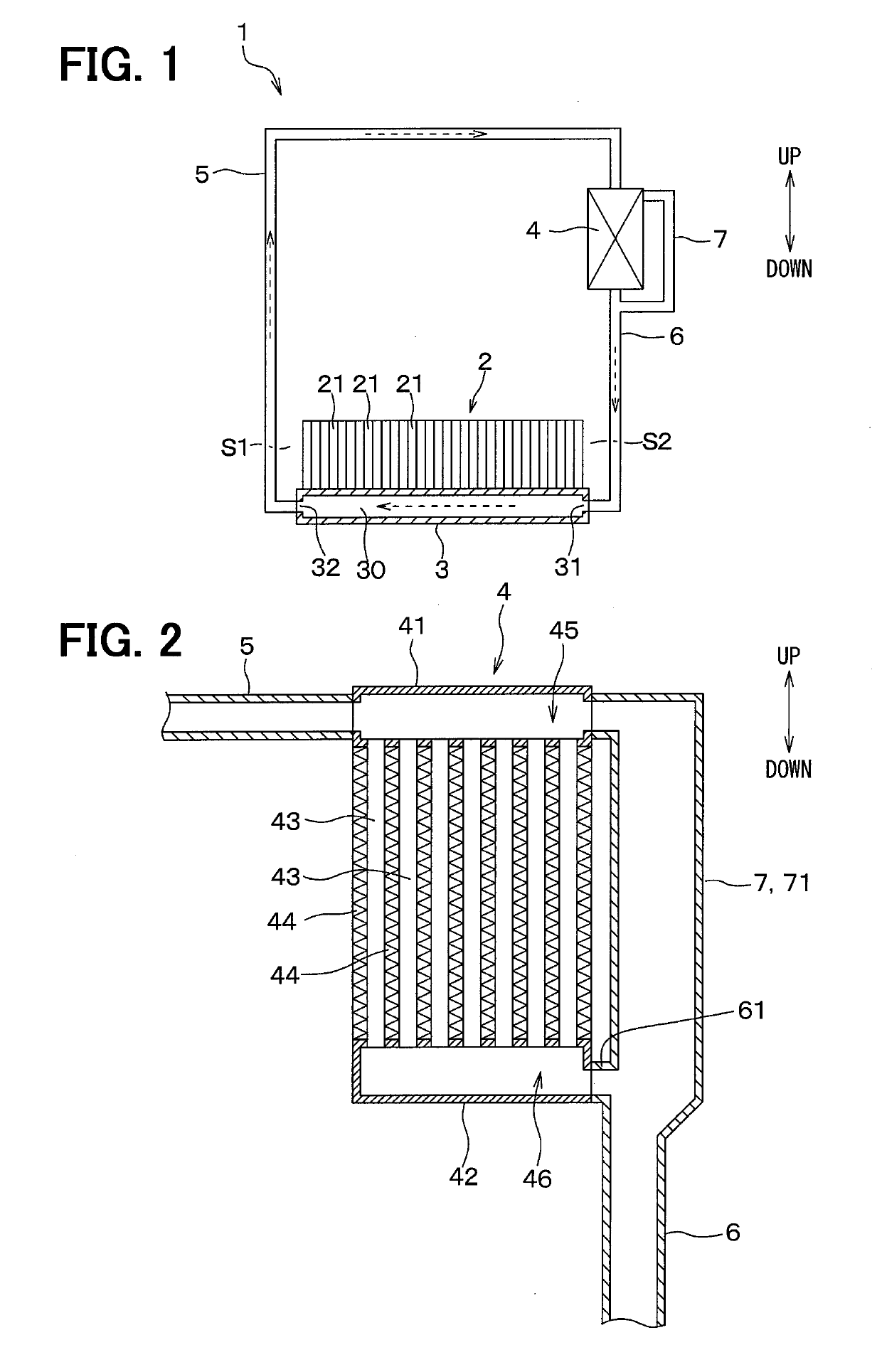
[0031]A first embodiment will be described below with reference to the accompanying drawings. A device temperature regulator of the present embodiment regulates the temperature of a target device, i.e., an electric device, such as an electrical storage device or an electronic circuit, mounted on electrically-driven vehicles, including electric vehicles and hybrid vehicles, by cooling the target device. In the drawings, arrows indicating up and down represent upward and downward directions of gravitational force when the device temperature regulator is mounted on a vehicle and the vehicle is stopped at a horizontal plane.

[0032]First, the target device to be temperature-regulated by a device temperature regulator 1 of the present embodiment will be described.

[0033]As shown in FIG. 1, the target device to be temperature-regulated by the device temperature regulator 1 of the present embodiment is an assembled battery 2 (hereinafter referred to as a “battery”). The target device may be a...

second embodiment

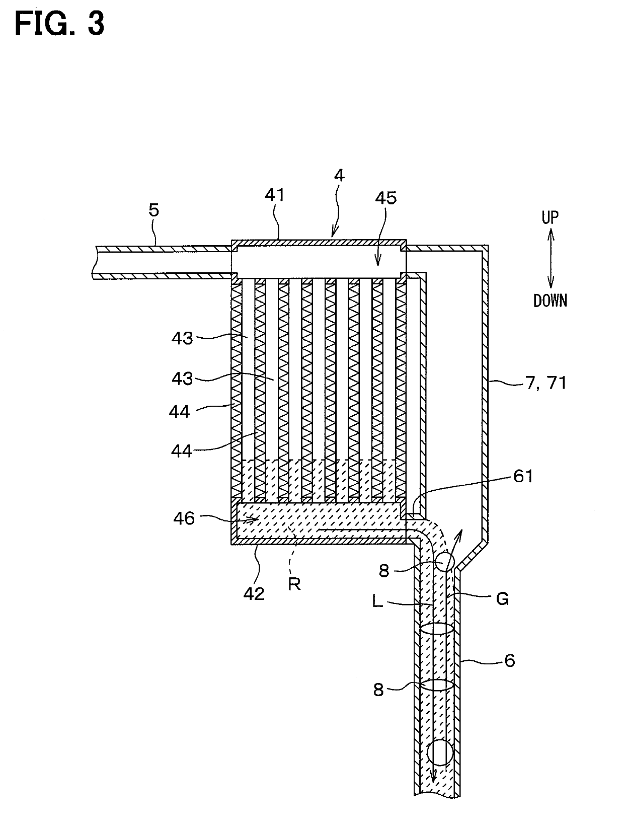
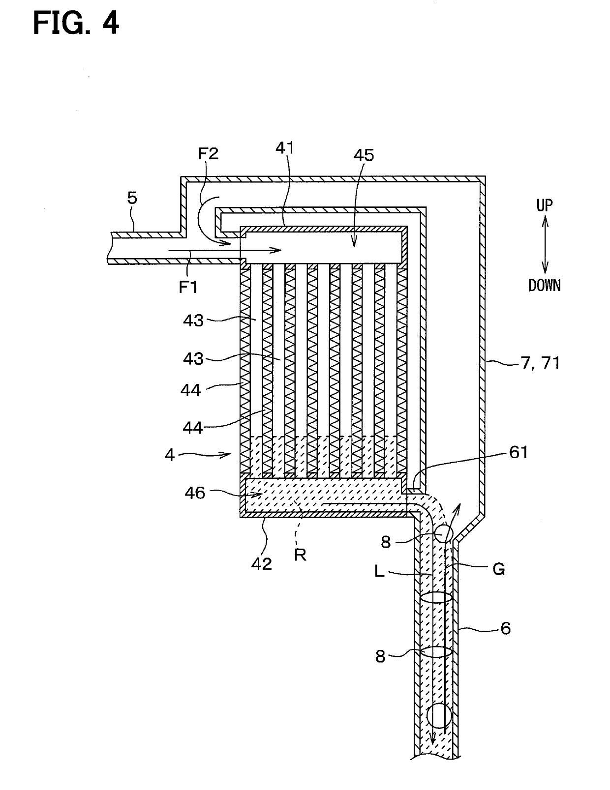
[0065]A second embodiment will be described below. The second embodiment is substantially the same as the first embodiment except that the configuration of the outer bypass passage 71 is changed with respect to that of the first embodiment, and thus only differences from the first embodiment will be described.

[0066]As shown in FIG. 4, in the second embodiment, the outer bypass passage 71 has one end connected to the liquid-phase passage 6 and the other end connected to the gas-phase passage 5. When the refrigerant boils in the evaporator 3 and is condensed in the condenser 4 due to a temperature difference between the evaporator 3 and the condenser 4, the flow of the gas-phase refrigerant directed from the evaporator 3 to the condenser 4 is generated in the gas-phase passage 5, as indicated by an arrow F1 in FIG. 4. Thus, the other end of the outer bypass passage 71 is connected to the gas-phase passage 5, so that the gas-phase refrigerant flowing through the outer bypass passage 71...

third embodiment

[0067]A third embodiment will be described below. The third embodiment is substantially the same as the first embodiment except that the configuration of the condenser 4 is changed with respect to that of the first embodiment, and thus only differences from the first embodiment will be described.

[0068]As shown in FIG. 5, in the third embodiment, the condenser 4 is configured of a sealed case, and does not include the upper tank, the lower tank, and the heat exchange tubes described in the first and second embodiments. A heat sink 47 configured of a plurality of plate-shaped members is provided on the upper outer side of the condenser 4. Each of the condenser 4 and the heat sink 47 is preferably made of a material having excellent thermal conductivity, such as aluminum or copper. The shape and size of each of the condenser 4 and the heat sink 47 can be arbitrarily set in accordance with a space on the vehicle where each of the condenser 4 and heat sink 47 is mounted.

[0069]The gas-pha...


PUM

PropertyMeasurementUnit
temperatureaaaaaaaaaa
flow rateaaaaaaaaaa
inner diameteraaaaaaaaaa

Abstract

An evaporator includes a fluid chamber in which a working fluid flows. A condenser includes a gas-phase portion in which the working fluid evaporated in the evaporator flows and a liquid-phase portion in which the working fluid from the gas-phase portion, condensed by heat exchange with an external medium, flows. A gas-phase passage causes the working fluid evaporated in the evaporator to flow to the condenser. A liquid-phase passage causes the working fluid condensed in the condenser to flow to the evaporator. A bypass passage has one end connected to the liquid-phase portion of the condenser or the liquid-phase passage and another end connected to the gas-phase portion of the condenser or the gas-phase passage. A flow rate of a liquid-phase working fluid per unit volume in the bypass passage is smaller than a flow rate of a liquid-phase working fluid per unit volume in the liquid-phase portion of the condenser or the liquid-phase passage.

Description

CROSS REFERENCE TO RELATED APPLICATION[0001]This application is based on Japanese Patent Application No. 2016-176783 filed on Sep. 9, 2016, the contents of which are incorporated herein by reference in its entirety.FIELD OF THE INVENTION[0002]The present disclosure relates to a device temperature regulator that regulates a temperature of a target device.BACKGROUND ART[0003]In recent years, a technique of using thermosiphon in a device temperature regulator has been studied to regulate the temperature of electric devices, including electrical storage devices mounted on electrically-driven vehicles, such as electric vehicles and hybrid vehicles.[0004]The device temperature regulator described in Patent Document 1 includes an evaporator provided on a side surface of a battery as the electrical storage device and a condenser provided above the evaporator. The evaporator and the condenser are annually connected by two pipes, in which a refrigerant as a working fluid is enclosed. In the d...

Claims


Application Information

Patent Timeline
Patent Type & Authority Applications(United States)
IPC IPC(8): F28D15/02H01M10/613H01M10/625H01M10/6556H01M10/6569H05K7/20
CPCF28D15/025F28D15/0266H01M10/613H01M10/625H01M10/6556H01M10/6569H05K7/20309H05K7/20318H05K7/20327H01M2220/20F28D15/02H05K7/20Y02E60/10F28D15/06H01M10/663H01M10/6568H01M10/617
Inventor YOSHINORI, TAKESHIYAMANAKA, TAKASHIKATO, YOSHIKITAKEUCHI, MASAYUKIMIURA, KOJIOMI, YASUMITSU
Owner DENSO CORP
Why Eureka
Try Eureka