Unambiguous Interferometer Radar Architecture

a radar and interferometer technology, applied in the field of radar systems, can solve the problems of unambiguous target position estimation for any target, non-uniform distribution of virtual sub-apertures, etc., and achieve the effect of maximum accuracy and minimal ambiguity

Inactive Publication Date: 2019-07-18
SRC INC
View PDF0 Cites 0 Cited by
  • Summary
  • Abstract
  • Description
  • Claims
  • Application Information

AI Technical Summary

Benefits of technology

[0004]The present invention is a transmit-receive radar system that includes the ability to search a sub-aperture pattern for the peak response without having to retransmit beams. More specifically, the radar system includes an antenna having a plurality of sub-apertures that are aligned in an offset and off-centered pattern, wherein the antenna is configured to transmit and receive separate waveforms from each aperture, wherein each waveform has the same center frequency and bandwidth. The radar system also includes a digital signal processor coupled to the antenna and programmed to decode each of the separate waveforms received from each of the plurality of sub-apertures to provide a single dwell instantaneous angular estimation of a target location. Each waveform may be coded to be separable from each other waveform when received. The antenna may be configured so that each waveform will be received by each sub-aperture to provide a plurality of independent data streams equal to the number of plura

Problems solved by technology

The pattern of the plurality of sub-apertures may result in unambiguous target position estimation for any target within a beamspace of the an

Method used


Image

  • Unambiguous Interferometer Radar Architecture
  • Unambiguous Interferometer Radar Architecture
  • Unambiguous Interferometer Radar Architecture

Examples


Embodiment Construction

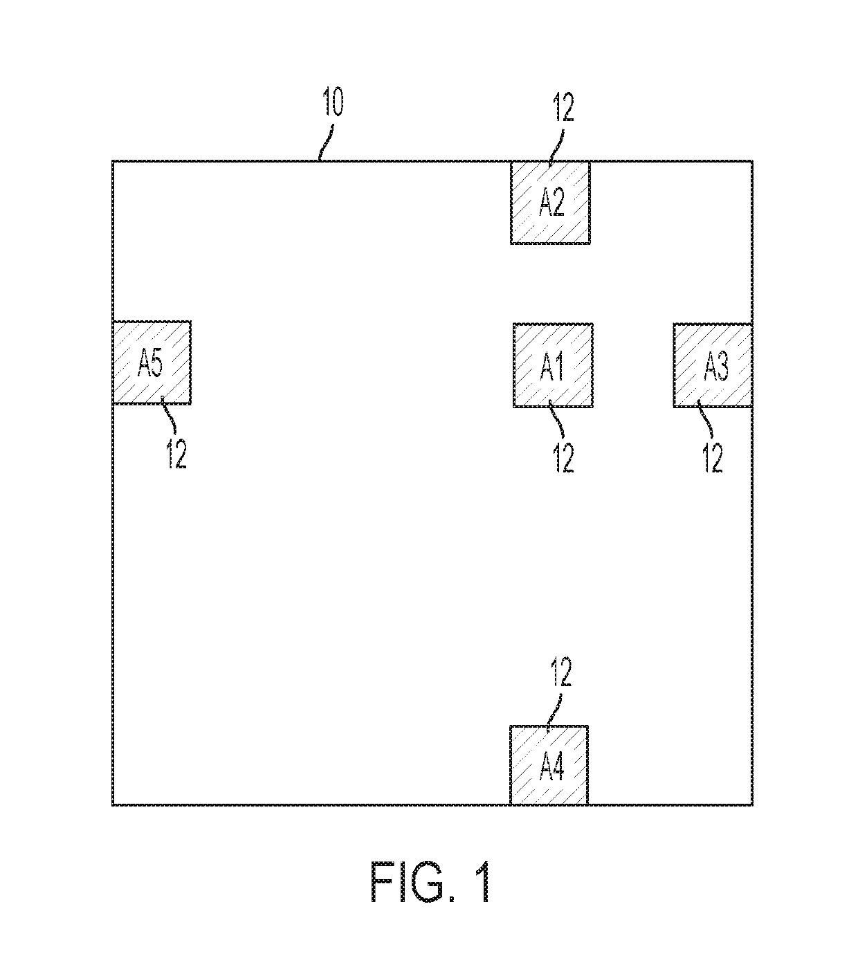
[0018]Referring to the figures, wherein like numeral refer to like parts throughout, there is seen in FIG. 1 an exemplary MIMO interferometer antenna system 10 having five sub-apertures 12, aligned in an offset, off-centered cross pattern according to the present invention to resolve targets within the entire sub-aperture beamspace, and to do so unambiguously. A separate waveform may be transmitted from each sub-aperture 12 simultaneously. Thus, system 10 of FIG. 1 assumes N separate waveforms are transmitted from each sub-aperture (or “aperture”), where N is the number of antenna sub-apertures 12. The waveforms are all of the same center frequency and bandwidth, and are coded such that they are separable (orthogonal) on receive. For example, the separability may be achieved via constant amplitude, phase coded waveforms, frequency coding, time sequencing, or other approaches, with each having varying benefits and challenges known in the art such that the approach can be selected as ...


PUM


Abstract

A transmit-receive radar system having multiple sub-apertures aligned in an offset, off-centered cross pattern that allows for searching of a sub-aperture pattern for the peak response without having to retransmit beams. The placement of the physical apertures combined with the use of MIMO operations provides a non-uniform distribution of virtual sub-apertures that suppresses ambiguous grading lobes and maintains angle resolution in a manner equivalent to that of non-MIMO approaches. As a result, target detection is enabled within a significantly larger angular area than in a non-MIMO configuration.

Description

CROSS-REFERENCE TO RELATED APPLICATIONS[0001]The present application claims priority to U.S. Provisional Application No. 62 / 594,732, filed on Dec. 5, 2017.BACKGROUND OF THE INVENTION1. Field of the Invention[0002]The present invention relates to radar systems and, more particularly, to an active radiofrequency (RF) sensor composed of a sparse array of sub-apertures.2. Description of the Related Art[0003]Conventional interferometry approaches include sparse array, high angle resolution RF sensors used by the astronomy community, but these systems are receive only. A typical MIMO system produces a continuous, virtual array of two-way (transmit-receive) phase centers with only one transmit array and several receive arrays (or vice versa). These systems can produce very low side-lobe two-way patterns, however, the receive arrays are not widely separated and thus provide inferior angle estimation.BRIEF SUMMARY OF THE INVENTION[0004]The present invention is a transmit-receive radar system...

Claims


Application Information

Patent Timeline
IPC IPC(8): G01S7/28H01Q21/00H01Q21/06G01S13/68
CPCG01S7/2813H01Q21/0025H01Q21/061G01S13/68
Inventor CULKIN, DANIEL R.BROWN, DANIEL T.SCHUMAN, HARVEY K.
Owner SRC INC
Why Eureka
Try Eureka