Acoustic wave filter device, multiplexer, radio-frequency front end circuit, and communication device

a technology of acoustic wave filter and amplification, which is applied in the direction of impedence networks, electrical devices, transmission, etc., can solve the problem of reducing the band width of the attenuation band, and achieve the effect of increasing the attenuation band width

Active Publication Date: 2019-07-18
MURATA MFG CO LTD
View PDF0 Cites 1 Cited by
  • Summary
  • Abstract
  • Description
  • Claims
  • Application Information

AI Technical Summary

Benefits of technology

[0008]Accordingly, the present disclosure was made in order to solve this problem and it is an object thereof to provide an acoustic wave filter device and so forth that can increase the attenuation band width when switching the frequency of a pass band and the frequency of an attenuation band to lower frequencies.
[0052]With the acoustic wave filter device and so forth according to the present disclosure, the attenuation band width can be increased when the frequency of the pass band and the frequency of the attenuation band are switched to lower frequencies.

Problems solved by technology

However, in the above-described configuration of the related art, in the case where the inductance values of paths that connect parallel arm resonators and switches in the parallel arms of the acoustic wave filter device are identical, there is a problem in that the band width of an attenuation band is decreased when the frequency of the pass band and the frequency of the attenuation band are shifted toward the low-frequency side by switching a switch.

Method used


Image

  • Acoustic wave filter device, multiplexer, radio-frequency front end circuit, and communication device
  • Acoustic wave filter device, multiplexer, radio-frequency front end circuit, and communication device
  • Acoustic wave filter device, multiplexer, radio-frequency front end circuit, and communication device

Examples


embodiment 1

Modification of Embodiment 1

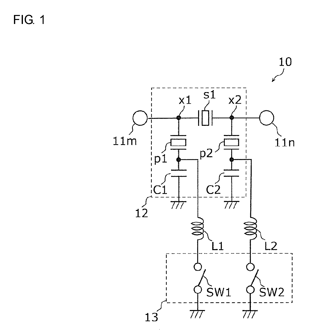
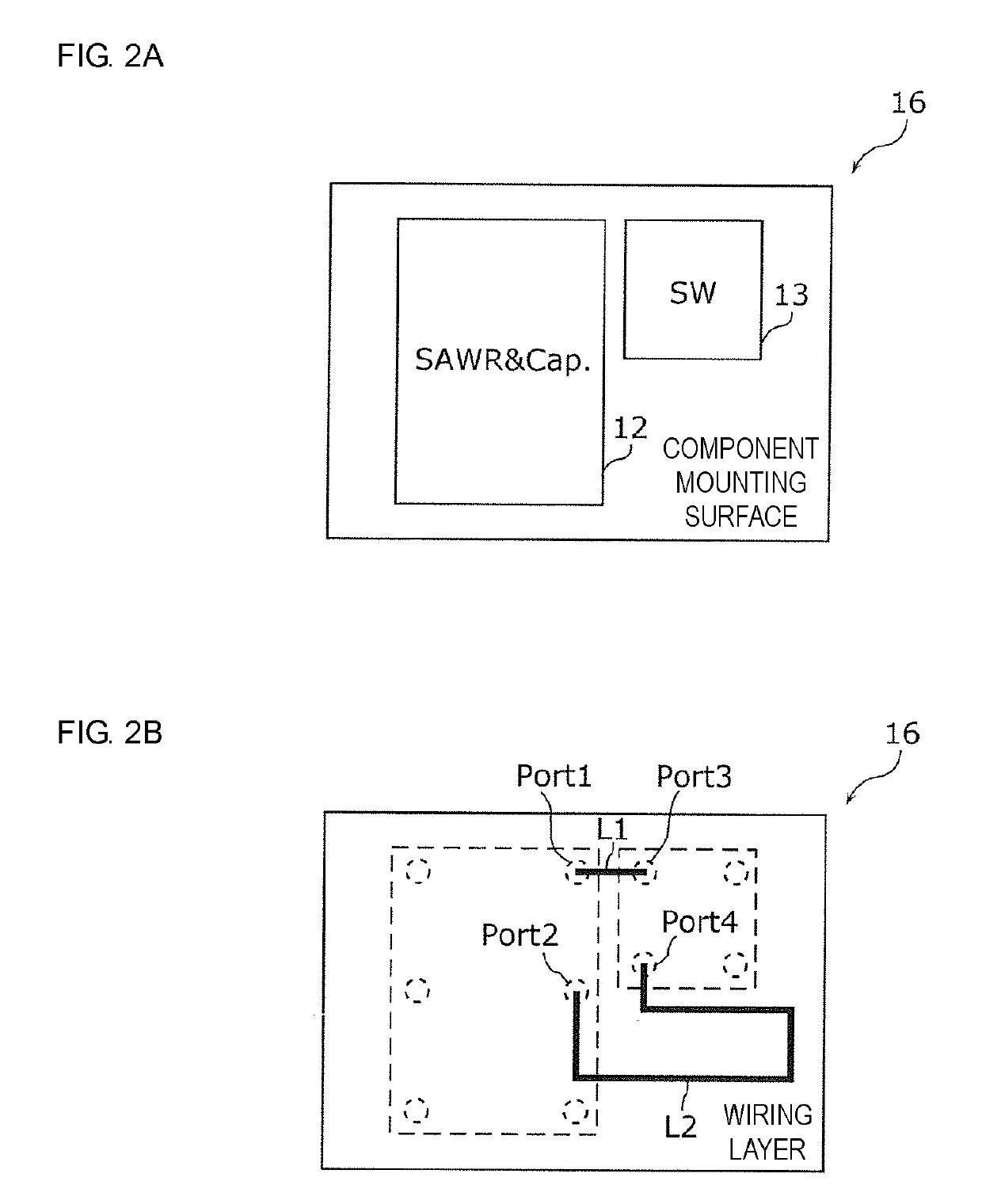
[0144]In the above-described embodiment, the first inductance value of the inductor L1 and the second inductance value of the inductor L2 are different from each other due to the length of the first wiring line and the length of the second wiring line being different from each other. However, the first inductance value and the second inductance value may be made different from each other by making the width (line width) of the first wiring line and the width (line width) of the second wiring line different from each other.

[0145]In addition, the first inductance value of the inductor L1 in the first parallel arm resonance circuit connected to the node x1 that is close to the input / output terminal 11m, which is the input terminal, is preferably smaller than the second inductance value. Consequently, the first inductance value can be made smaller than the second inductance value by making the line width of the first wiring line, which is the inductor L1, lar...

embodiment 2

[0152]The filters (acoustic wave filter devices) according to the above-described embodiment and modification are tunable filters in which the pass band can be changed. As filters according to embodiment 2, application examples of such a tunable filter will be described using application examples 1 to 4.

application example 1

[0153]FIG. 8 is a circuit configuration diagram of a filter 20A according to application example 1 of embodiment 2.

[0154]Compared with the filter 10 illustrated in FIG. 1, the filter 20A illustrated in the figure further includes a third parallel arm resonance circuit connected in parallel with the first parallel arm resonance circuit between the node x1 and ground and a fourth parallel arm resonance circuit connected in parallel with the second parallel arm resonance circuit between the node x2 and ground. The third parallel arm resonance circuit includes a parallel arm resonator p3 (third parallel arm resonator) that is connected to the node x1, and the fourth parallel arm resonance circuit includes a fourth parallel arm resonator that is connected to the node x2. In addition, the resonant frequency of the parallel arm resonator p1 (referred to as fp1) is different from the resonant frequency of the parallel arm resonator p3 (referred to as fp3), and the resonant frequency of the ...


PUM


Abstract

A filter includes a series arm resonator, a first parallel arm resonance circuit, and a second parallel arm resonance circuit. The first parallel arm resonance circuit includes: a first parallel arm resonator connected to a first node; a first capacitor and a first switch connected together in parallel and connected in series with the first parallel arm resonator; and a first inductor provided on a path connecting the node and ground to each other via the first switch. The second parallel arm resonance circuit includes: a second parallel arm resonator connected to a second node; a second capacitor and a second switch connected together in parallel and connected in series with the second parallel arm resonator; and a second inductor provided on a path connecting the second node and ground to each other via the second switch. The first and second inductor have different inductance values.

Description

[0001]This is a continuation of International Application No. PCT / JP2017 / 033977 filed on Sep. 20, 2017 which claims priority from Japanese Patent Application No. 2016-192348 filed on Sep. 29, 2016. The contents of these applications are incorporated herein by reference in their entireties.BACKGROUND OF THE DISCLOSUREField of the Disclosure[0002]The present disclosure relates to an acoustic wave filter device including a resonator, and to a multiplexer, a radio-frequency front end circuit, and a communication device.Description of the Related Art[0003]In the related art, acoustic wave filter devices that employ acoustic waves are widely used in band pass filters and the like that are arranged in the front end units of mobile communication devices. In addition, radio-frequency front end circuits and communication devices have been implemented that include a plurality of acoustic wave filter devices in order to support combinations such as multiple modes, multiple bands, and so on.[000...

Claims


Application Information

Patent Timeline
Patent Type & Authority Applications(United States)
IPC IPC(8): H03H9/64H03H9/72H03H9/02H03H9/17H03H9/205H03H9/54H04B1/525
CPCH03H9/64H03H9/72H03H9/02007H03H9/171H03H9/205H03H9/542H04B1/525H03H9/02102H03H9/568H03H9/605H03H9/6403H03H9/6483H03H9/706H03H9/725H04B1/006H04B1/403
Inventor TSUKAMOTO, HIDEKINOSAKA, KOJI
Owner MURATA MFG CO LTD
Why Eureka
Try Eureka