Piezoelectric transducer

a technology of piezoelectric transducers and transducers, applied in the field of piezoelectric transducers, can solve the problems of too weak piezoelectric signals to achieve high sensitivity, and achieve the effect of improving the sensing sensitivity of acoustic waves

Active Publication Date: 2019-07-18
MERRY ELECTRONICS (SHENZHEN) CO LTD
View PDF10 Cites 1 Cited by
  • Summary
  • Abstract
  • Description
  • Claims
  • Application Information

AI Technical Summary

Benefits of technology

[0006]The disclosure provides a piezoelectric transducer that effectively enhances sensing sensitivity of acoustic waves and balances static pressure inside the transducer.
[0018]Based on the foregoing, in the disclosure, the piezoelectric layer of the piezoelectric transducer is divided into the displacement zone and the plurality of sensing zones, and the stiffening structure is disposed on the bottom of the displacement zone to strengthen rigidity. When the acoustic wave from the outside acts on the piezoelectric transducer, the displacement zone of the piezoelectric layer generates an up-and-down displacement such that the deformation of the piezoelectric layer is mostly concentrated on the plurality of sensing zones. Accordingly, each of the sensing zones may generate a stronger electrical signal so as to obtain a better sensing sensitivity of acoustic waves. Besides, the gaps between each of the sensing zones may communicate the chamber with the external environment so as to balance the pressure inside the chamber, thereby preventing the generation of erroneous signals due to the change of the outside atmospheric pressure.

Problems solved by technology

As a result, the electrical signal read by the piezoelectric device is too weak to achieve high sensitivity.

Method used


Image

  • Piezoelectric transducer
  • Piezoelectric transducer
  • Piezoelectric transducer

Examples


Embodiment Construction

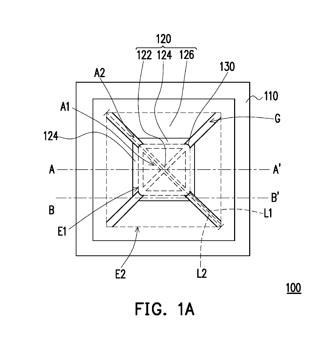
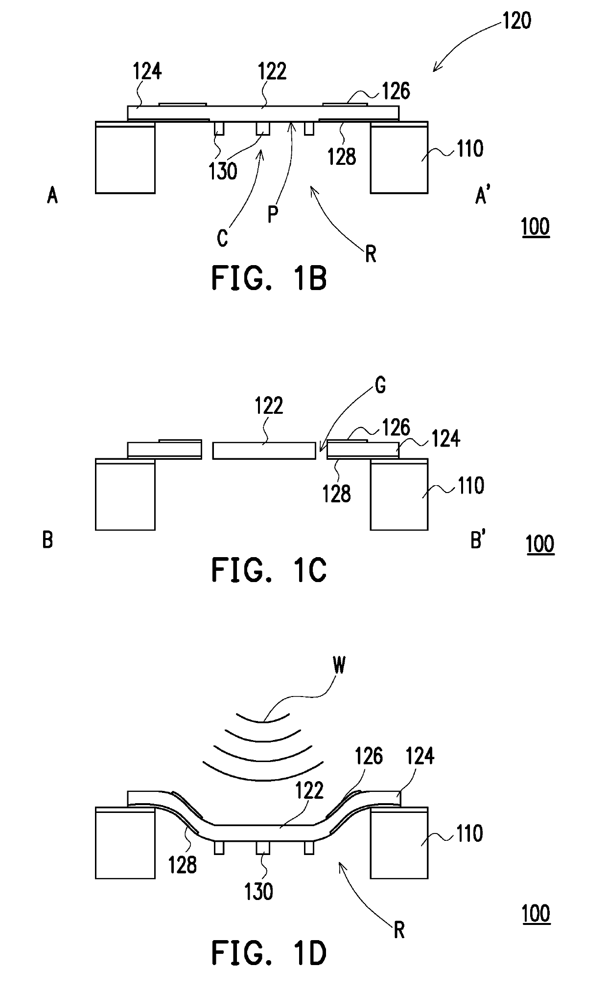
[0031]FIG. 1A is a schematic top view of a piezoelectric transducer according to an embodiment of the disclosure. FIG. 1B is a schematic cross-sectional view of the piezoelectric transducer of FIG. 1A taken along the line A-A′. FIG. 1C is a schematic cross-sectional view of the piezoelectric transducer of FIG. 1A taken along the line B-B′. FIG. 1D is a view showing a piezoelectric layer of FIG. 1B in a deformed state, being acted on by an acoustic wave.

[0032]With reference to FIG. 1A to FIG. 1C, a piezoelectric transducer 100 is adapted to be disposed in an electronic device. The electronic device may be, for example, a cell phone, a tablet computer or other handheld electronic devices, and the piezoelectric transducer 100 may be applied to, for example, a speaker, a microphone or other similar transduction devices.

[0033]The piezoelectric transducer 100 includes a substrate 110, a piezoelectric layer 120, and a stiffening structure 130. The substrate 110 is, for example, made of pol...


PUM


Abstract

A piezoelectric transducer including a substrate, a piezoelectric layer and a stiffening structure is provided. The substrate has a chamber. The piezoelectric layer has a displacement zone, a plurality of sensing zones, a plurality of gaps, a plurality of top electrodes, and a plurality of bottom electrodes. The displacement zone is located over the chamber. The sensing zones are surroundingly connected to an outer edge of the displacement zone and are located over the chamber. The gaps are each formed between any adjacent two of the plurality of sensing zones, and each of the gaps communicates with the chamber. The top electrodes are each disposed on a top surface of each of the sensing zones. The bottom electrodes are each disposed on a bottom surface of each of the sensing zones. The stiffening structure is disposed on a bottom of the displacement zone.

Description

CROSS-REFERENCE TO RELATED APPLICATION[0001]This application claims the priority benefit of Taiwan application serial no. 107101353, filed on Jan. 15, 2018. The entirety of the above-mentioned patent application is hereby incorporated by reference herein and made a part of this specification.BACKGROUNDTechnical Field[0002]The disclosure relates to a piezoelectric transducer, and particularly relates to a piezoelectric transducer for sensing acoustic waves.Description of Related Art[0003]A microphone is a transducer that converts sound into electrical signals and includes a variety of forms such as moving coil, capacitive and piezoelectric. The piezoelectric microphone is a piezoelectric transducer made of a piezoelectric material. The piezoelectric material is characterized by the fact that mechanical vibrations acting on the piezoelectric material may be converted into electrical signals, or the voltage applied to the piezoelectric material may be converted into a deformation.[0004...

Claims


Application Information

Patent Timeline
Patent Type & Authority Applications(United States)
IPC IPC(8): H04R17/02H01L41/047H01L41/053H01L41/113
CPCH04R17/02H01L41/047H01L41/053H01L41/1132H01L41/1136H04R17/005H04R17/00H04R2201/003H10N30/306H10N30/302H10N30/87H10N30/88
Inventor CHEN, JEN-YICHANG, CHAO-SENJIANG, KAI-YUPENG, JUI-CHIN
Owner MERRY ELECTRONICS (SHENZHEN) CO LTD
Why Eureka
Try Eureka