Fixture for suppressing tool vibration on outer rim

a technology for suppressing tool vibration and fixing the outer rim, which is applied in the direction of manufacturing tools, metal-working machine components, transportation and packaging, etc., can solve the problems of tool vibration that is likely to occur, and achieve the effect of eliminating the vibration of the wheel rim, high elasticity, and eliminating the problem of tool vibration

Active Publication Date: 2019-07-25
CITIC DICASTAL
View PDF0 Cites 5 Cited by
  • Summary
  • Abstract
  • Description
  • Claims
  • Application Information

AI Technical Summary

Benefits of technology

[0004]The aim of the present invention is to provide a fixture for suppressing tool vibration on an outer rim.
[0008]In operation, as the wheel rotates at a high speed, the steel balls are thrown outwardly by centrifugal force, and thus drive the rubber strip to move outwardly to compress the inner rim of the wheel. The rubber strip in the compressed state is of high elasticity and can effectively eliminate the vibration of the wheel rim during machining, which can effectively eliminate the problem of tool vibration on the outer rim.
[0010]In actual use, during the process of placing the wheel on the fixture, the positioning mandrel is positioned into the center hole of the wheel with tiny gaps being reserved between the rubber strip and the inner rim of the wheel, then the pressure claw compresses the wheel lip, and the wheel positioning operation is completed. Then, the machining of the wheel begins, and the wheel rotates at a high speed, with a result that the steel balls are thrown outwardly by the centrifugal force and thus drive the rubber strip to move outwardly to compress the inner rim of the wheel. The rubber strip in the compressed state is of high elasticity and can effectively eliminate the vibration of the wheel rim during machining, which can effectively eliminate the problem of tool vibration on the outer rim.
[0011]The fixture in present invention can suppress tool vibration on the outer rim, and at the same time, has the characteristics of simple structure, convenient manufacture, stable performance and precision that can meet the machining requirement.

Problems solved by technology

In the machining process of a wheel outer rim, the problem of tool vibration is likely to occur due to the vibration of a machine tool and the instable fixation of the wheel on the machine tool.

Method used


Image

  • Fixture for suppressing tool vibration on outer rim
  • Fixture for suppressing tool vibration on outer rim
  • Fixture for suppressing tool vibration on outer rim

Examples


Embodiment Construction

[0018]The details and working conditions of the specific device according to the present invention will be described in detail below in combination with the drawings.

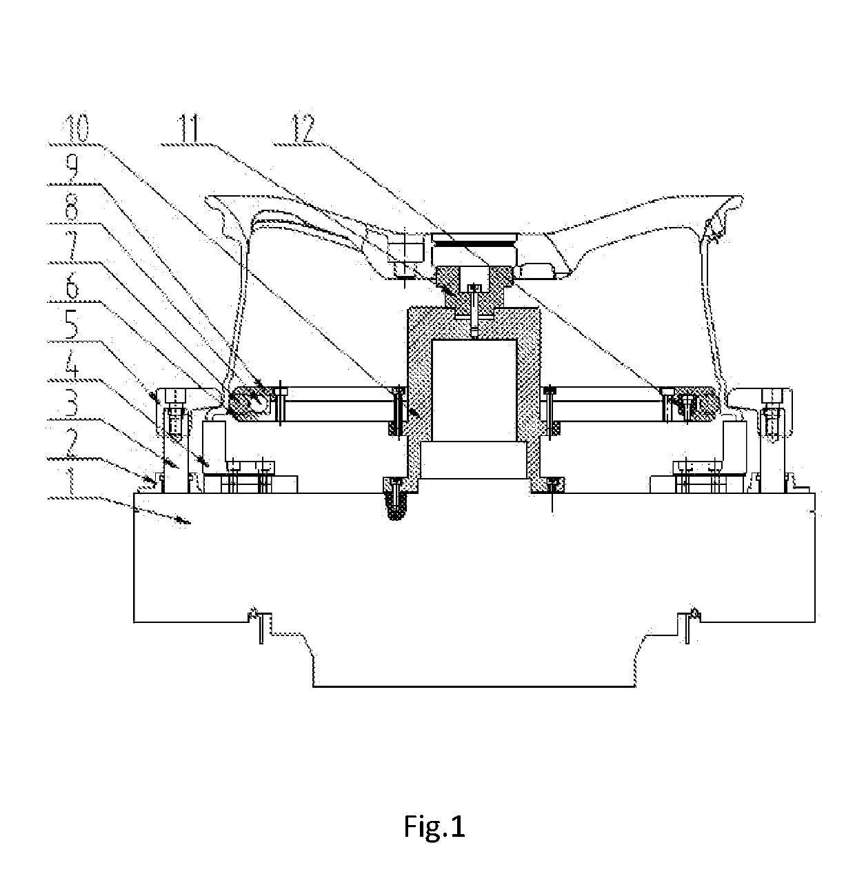
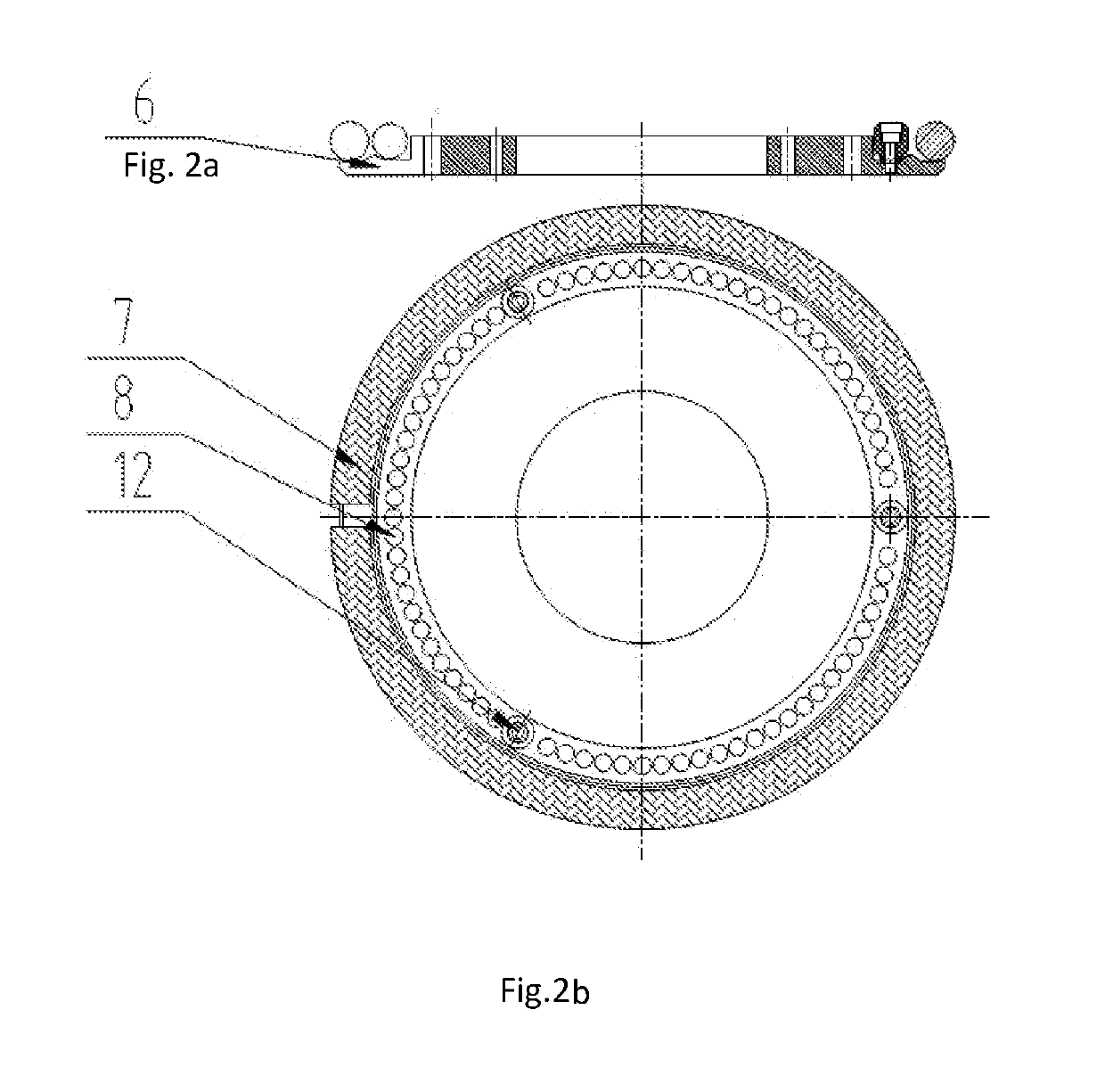
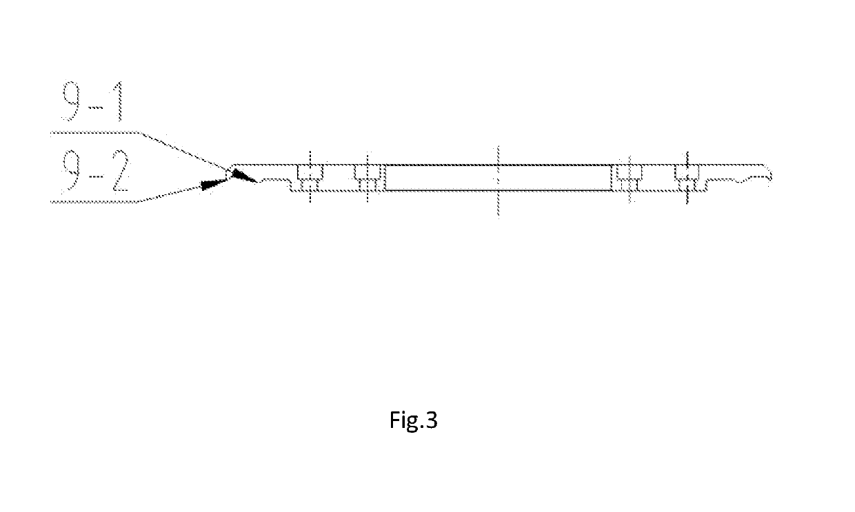
[0019]As shown in FIGS. 1-5, a fixture for suppressing tool vibration on an outer rim according to the present invention comprises a chuck 1, a pressure claw base 2, a pressure claw shaft 3, an end face block 4, a pressure claw 5, a lower pressure plate 6, a rubber strip 7, steel balls 8, an upper pressure plate 9, a base 10, a positioning mandrel 11 and limiting columns 12. The pressure claw base 2, the end face block 4 and the base 10 are installed on the chuck 1, the positioning mandrel 11 is installed on the base 10, and the pressure claw 5 is installed on the chuck 1 by means of the pressure claw shaft 3 and the pressure claw base 2. The lower pressure plate 6 is fixed on the base 10, and the limiting columns 12 and the upper pressure plate 9 are installed on the lower pressure plate 6, with the steel balls 8 and t...


PUM


Abstract

A fixture for suppressing tool vibration on an outer rim, wherein a pressure claw base, an end face block and a base are installed on the chuck, and the pressure claw is installed on the chuck; a lower pressure plate is fixed on the base, limiting columns and an upper pressure plate are installed on the lower pressure plate, with steel balls and a rubber strip being enclosed in a space formed by the lower pressure plate and the upper pressure plate; and a rubber strip is enclosed in an annular groove formed by a jaw A and a jaw B, and can move radially in the groove. The fixture in the present invention is configured to counteract the vibration of the wheel rim during machining, and thus can effectively eliminate the problem of tool vibration on the outer rim.

Description

CROSS REFERENCE TO RELATED APPLICATION[0001]This application claims priority to Chinese Patent Application No. 201810058688, entitled FIXTURE FOR SUPPRESSING TOOL VIBRATION ON OUTER RIM and filed on Jan. 22, 2018, which is incorporated herein by reference in its entirety and for all purposes.FIELD OF THE INVENTION[0002]The present invention relates to a machining device, specifically to a fixture for machining wheel.BACKGROUND OF THE INVENTION[0003]In the machining process of a wheel outer rim, the problem of tool vibration is likely to occur due to the vibration of a machine tool and the instable fixation of the wheel on the machine tool.SUMMARY OF THE INVENTION[0004]The aim of the present invention is to provide a fixture for suppressing tool vibration on an outer rim.[0005]In order to fulfill the above aim, the technical solution of the present invention includes a fixture for suppressing tool vibration on an outer rim according to the present invention, comprising a chuck, a pre...

Claims


Application Information

Patent Timeline
Patent Type & Authority Applications(United States)
IPC IPC(8): B23Q3/06B23Q11/00B21D53/30
CPCB23Q3/062B23Q11/0032B21D53/30B23Q3/06B23Q3/12
Inventor LIU, WEIDONGJIANG, XIAOYUWANG, XUESONGZHANG, SHENGCHAOCHANG, HAIPINGWANG, YINGFENGYAO, DAN
Owner CITIC DICASTAL
Why Eureka
Try Eureka