Dynamic compensation of a robot arm mounted on a flexble arm

Pending Publication Date: 2019-07-25
FASTBRICK IP PTY LTD
View PDF3 Cites 25 Cited by
  • Summary
  • Abstract
  • Description
  • Claims
  • Application Information

AI Technical Summary

Benefits of technology

[0055]The arrangements of the invention may achieve a high degree of dynamic motion quality and position tolerance over a large size of workspace. This results in smoother motion for end effectors located a

Problems solved by technology

A problem with this methodology is that the working coordinate system cannot be shifted after the program has been written.
The disadvantage with this arrangement was that the actual position of the end effector (or laid brick) in ground coordinates was not obvious in the program that controlled the entire machine (because it is programmed in a different coordinate system, ie the robot arm base coordinate system).
The arrangement described in WO 2007/076581 went a long

Method used


Image

  • Dynamic compensation of a robot arm mounted on a flexble arm
  • Dynamic compensation of a robot arm mounted on a flexble arm
  • Dynamic compensation of a robot arm mounted on a flexble arm

Examples


Example

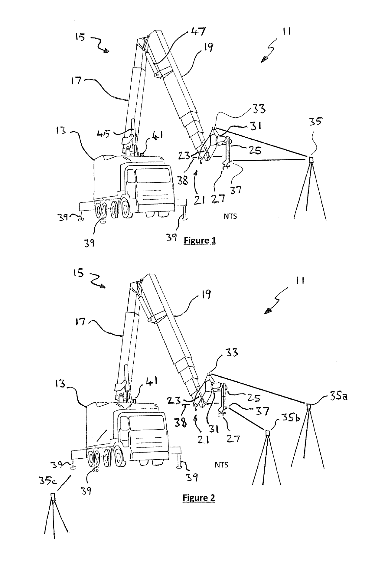
[0068]The control systems and methods of the invention have been developed by the inventor in connection with an automated brick laying machine 11. For a more detailed description of the brick laying machine, reference is made to the patent specification titled “Brick / Block Laying Machine Incorporated in a Vehicle” which is the subject of international patent application PCT / AU2017 / 050731, the contents of which are incorporated herein by cross-reference.

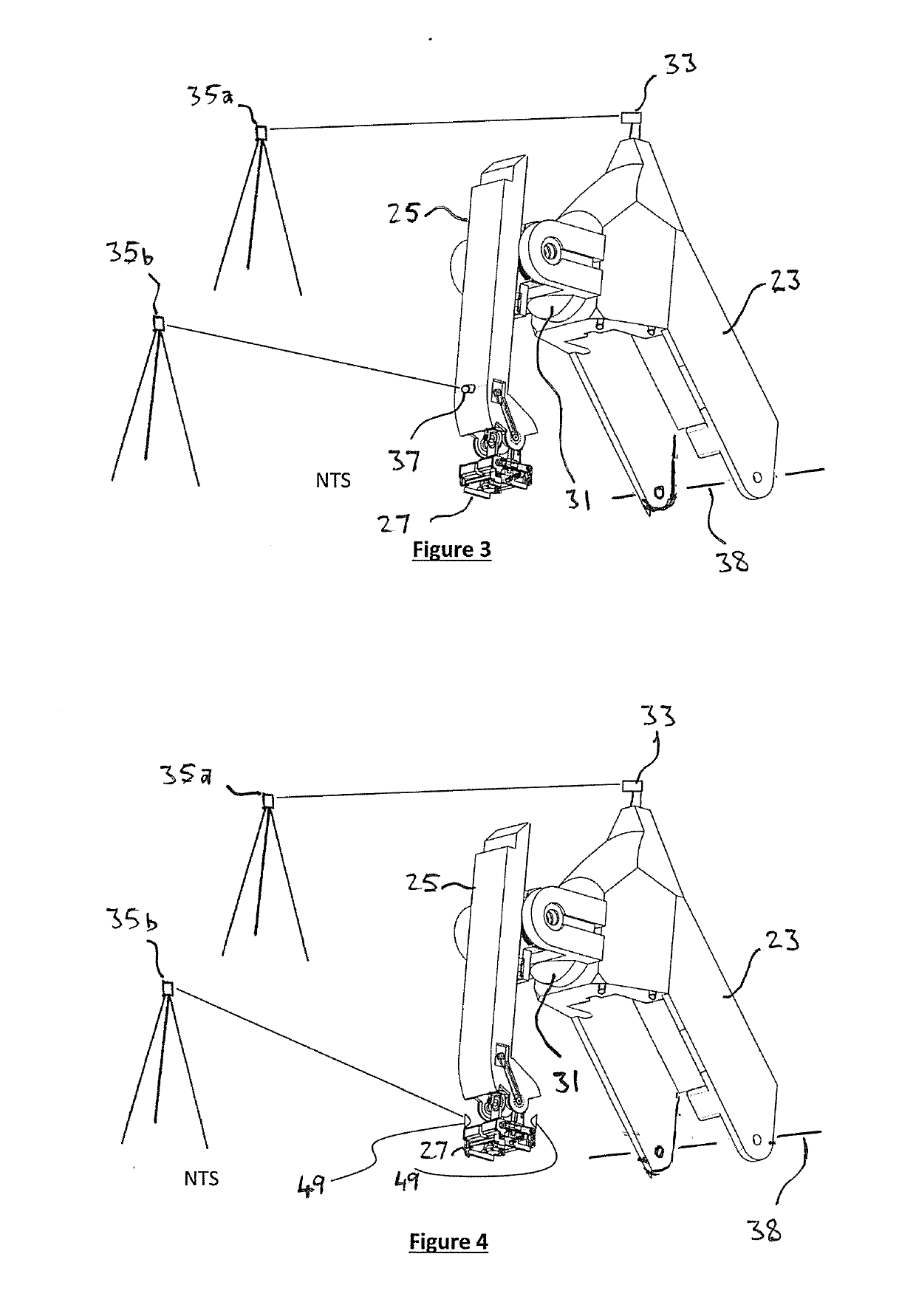
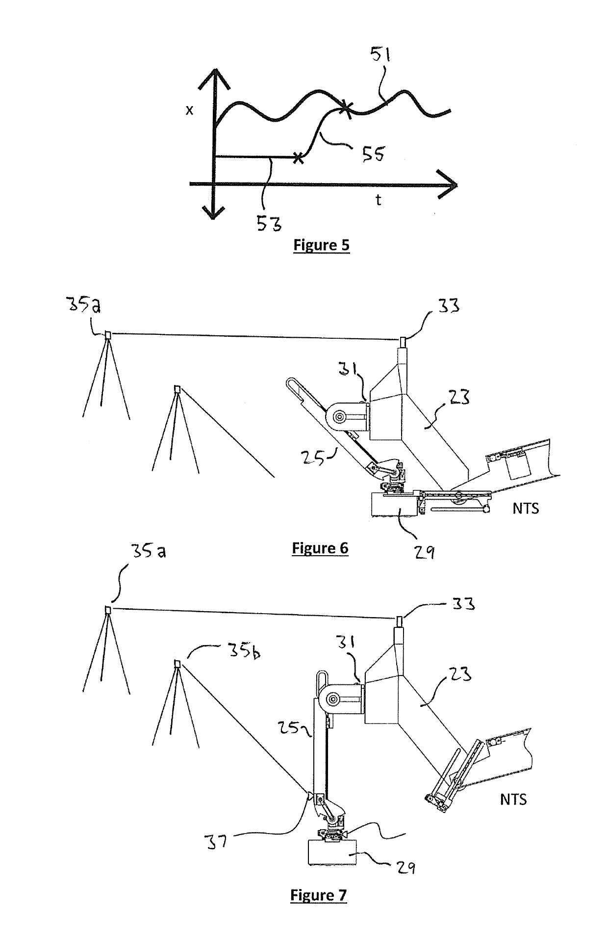
[0069]The automated brick laying machine 11 is built around a vehicle in the form of a truck 13 and has a base supporting a telescoping articulated boom assembly indicated generally at 15, comprising long telescopic boom 17 and telescopic stick 19. Mounted to the remote end 21 of the stick 19 is an end effector in the form of a laying head 23 that supports a 6 axis robot arm 25 that moves a further end effector 27 to manipulate the bricks 29. The robot arm 25 has a robot base 31, and mounted above the robot base 31 is a first target ...


PUM

PropertyMeasurementUnit
Angleaaaaaaaaaa
Degree of freedomaaaaaaaaaa
Dynamicaaaaaaaaaa

Abstract

A control system is described for a base supporting a telescoping articulated boom assembly indicated generally at 15, comprising long telescopic boom 17 and telescopic stick 19. Mounted to the remote end 21 of the stick 19 is an end effector in the form of a head 23 that supports a 6 axis robot arm 25 that moves a further end effector 27 to manipulate the items. The robot arm 25 has a robot base 31, and mounted above the robot base 31 is a first target in the form of a 6 degree of freedom (6 DOF) high data rate position sensor 33, that provides 6 DOF position coordinates, relative to a fixed ground reference 35, to a control system. Mounted on the end of the robot arm 25 immediately above the end effector 27 is a second target in the form of a 6 degree of freedom (6 DOF) high data rate position sensor 37, that provides 6 DOF position coordinates, relative to the fixed ground reference 35, to the control system. The fixed ground reference 35 tracks the sensor 33 and feeds data to the control system to move the head with slow dynamic response within range of work for the robot arm, and tracks the sensor 37 to control movement of the robotic arm 25 and end effector 27 with fast dynamic response.

Description

TECHNICAL FIELD[0001]This invention relates to control of an end effector on a flexible arm, and in particular to the improved control of the position of the end effector on a flexible arm such as a boom. The invention has particular application where a robot works over a large area and requires high precision.BACKGROUND ART[0002]The following discussion of the background art is intended to facilitate an understanding of the present invention only. It should be appreciated that the discussion is not an acknowledgement or admission that any of the material referred to was part of the common general knowledge as at the priority date of the application.[0003]The following definitions apply to terminology used throughout this patent specification. A robot arm is a programmable mechanical manipulator. In this specification a robot arm includes multi axis jointed arms, parallel kinematic robots (such as Stewart Platform, Delta robots), spherical geometry robots, Cartesian robots (orthogon...

Claims


Application Information

Patent Timeline
IPC IPC(8): B25J9/16
CPCB25J9/1635B25J9/1638G01S17/66G05B2219/40257G05B2219/45086B66C13/22E04G21/22G05B19/4097G06F2111/20G06F30/13B25J9/162Y02B10/30G05B2219/40513G05B2219/40298B25J9/1664G05B2219/39172G05B19/4182G05B19/41815G06F16/1734Y02P90/02H04W4/70G06F16/00B28D1/003B28D1/10B28D1/186B28D7/005B28D7/04B60P3/28G01C15/002G05B2219/35207B25J5/00B25J9/1612B25J9/1651B25J19/021B60P1/48E04F21/023G05B2219/39001B25J9/161B25J9/1684B25J9/1694B25J13/089B25J19/022B25J9/023B25J9/1633B25J9/1674E04B1/02B25J9/1679B25J9/1697E04B2/04G05B19/416
Inventor PIVAC, MARK
Owner FASTBRICK IP PTY LTD
Why Eureka
Try Eureka