
Hydrodynamic Intershaft Piston Ring Seal

Inactive Publication Date: 2019-07-25
GENERAL ELECTRIC CO
View PDF4 Cites 3 Cited by
  • Summary
  • Abstract
  • Description
  • Claims
  • Application Information

AI Technical Summary

Benefits of technology

The present invention provides a seal assembly for use in a gas turbine engine, which helps to seal high-pressure and low-pressure areas. The seal assembly includes a first end ring and a second end ring with a seal element positioned between them. The seal element is made up of a first hydrodynamic portion on the aft face of the first end ring and a second hydrodynamic portion on the forward face of the second end ring. The seal assembly is positioned between the inner shaft and the outer shaft, and it can be installed by coupling the end rings to the inner shaft. This helps to improve the performance and efficiency of the gas turbine engine.

Problems solved by technology

However, the carbon seals may directly contact the moving rotor shaft, which may reduce the wear life of the seals and require dedicated cooling thereof.
Further, labyrinth seals usually have more leakage compared to other seal types, such as piston ring seals.
Moreover, piston ring seals also are direct contact seals, having reduced wear life and increased cooling requirements like carbon seals, and cannot withstand the demands of relatively higher pressure differentials that arise in some engine applications.
Nevertheless, the use of multiple hydrodynamic seals instead of contact seals may increase the size, weight, cost, and installation complexity of the bearing compartment sealing system.

Method used


Image

  • Hydrodynamic Intershaft Piston Ring Seal
  • Hydrodynamic Intershaft Piston Ring Seal
  • Hydrodynamic Intershaft Piston Ring Seal

Examples


Embodiment Construction

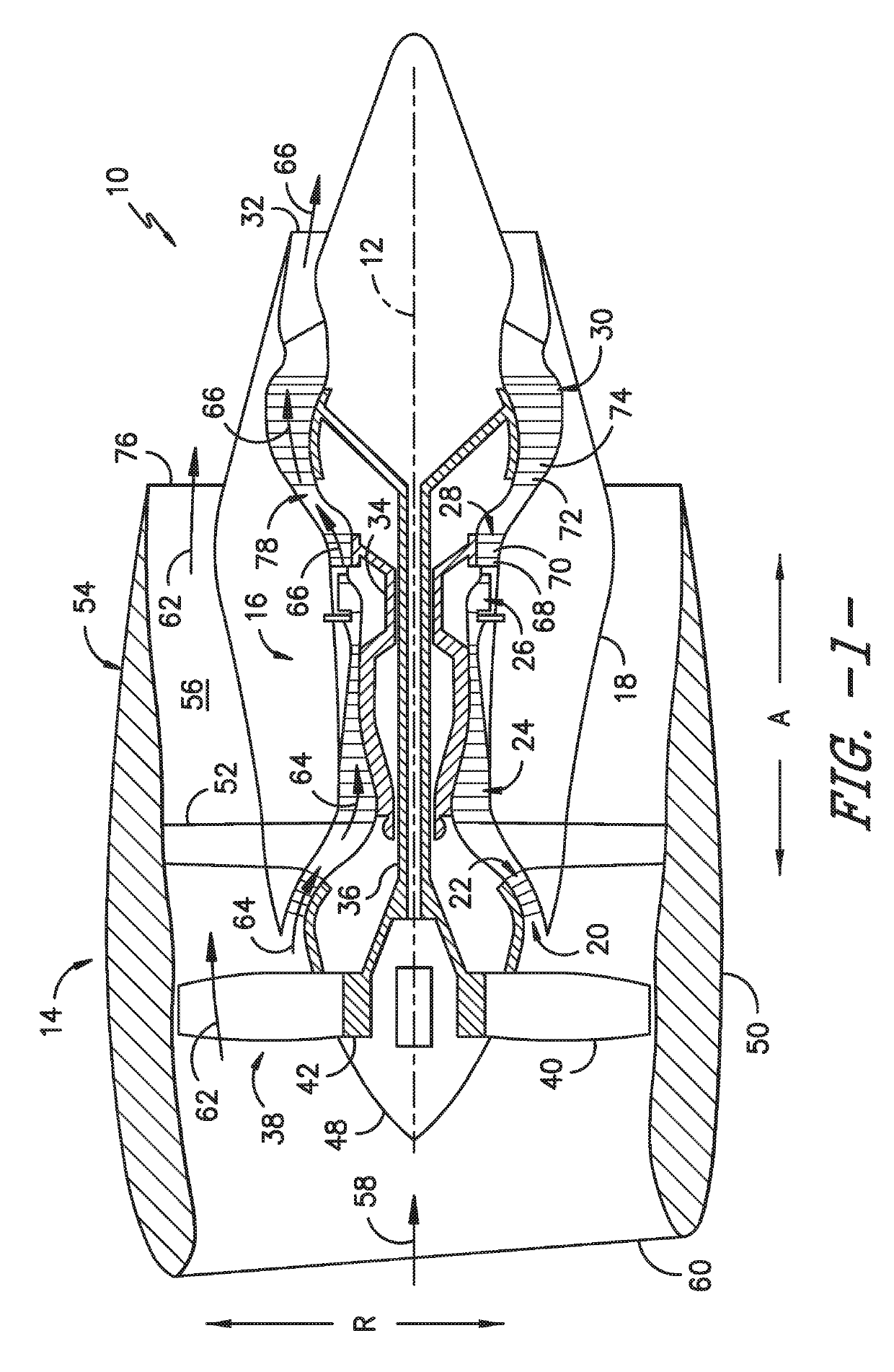
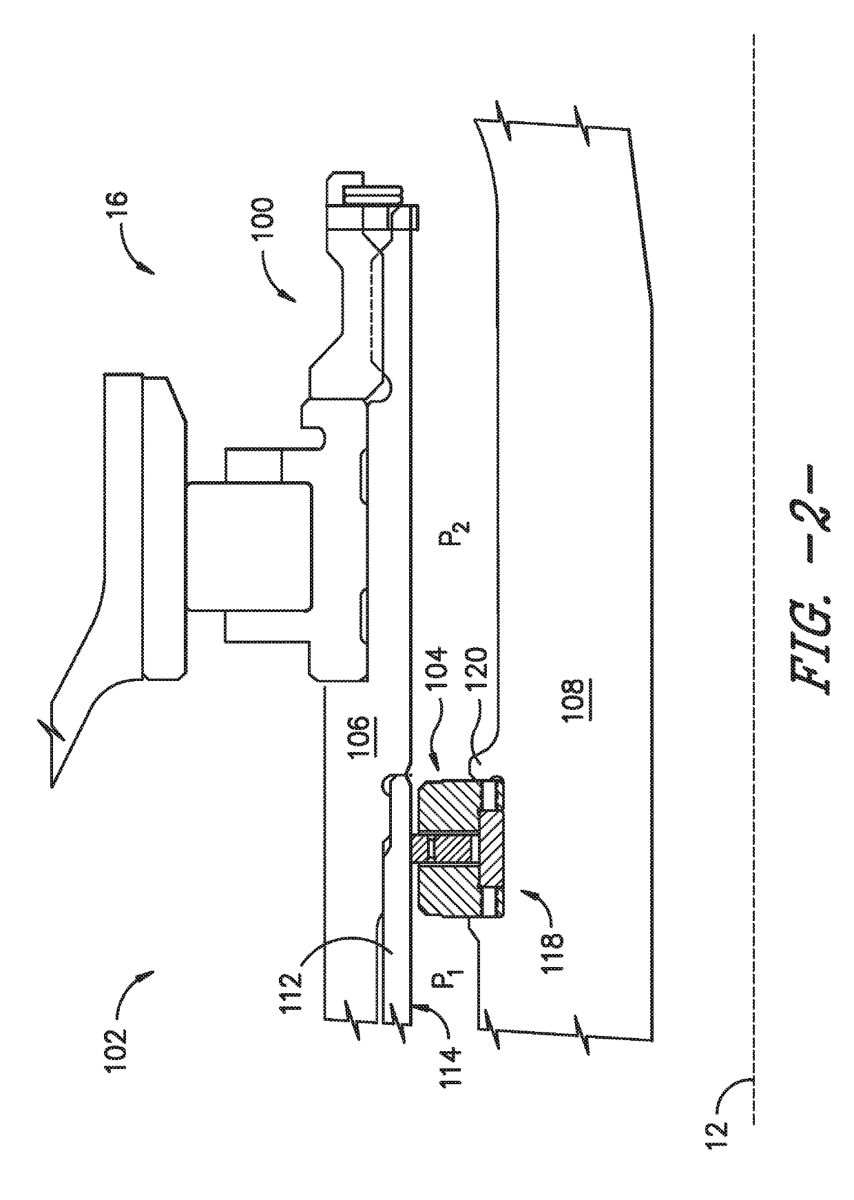
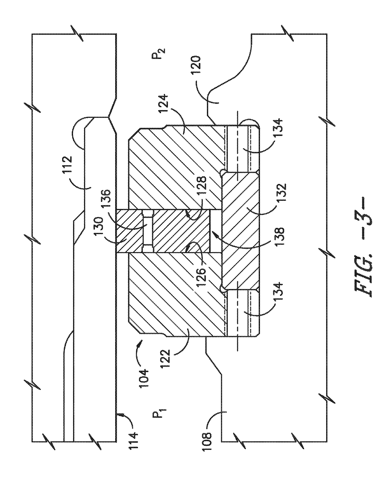
[0020]Reference will now be made in detail to present embodiments of the invention, one or more examples of which are illustrated in the accompanying drawings. The detailed description uses numerical and letter designations to refer to features in the drawings. Like or similar designations in the drawings and description have been used to refer to like or similar parts of the invention. As used herein, the terms “first,”“second,” and “third” may be used interchangeably to distinguish one component from another and are not intended to signify location or importance of the individual components. The terms “upstream” and “downstream” refer to the relative direction with respect to fluid flow in a fluid pathway. For example, “upstream” refers to the direction from which the fluid flows and “downstream” refers to the direction to which the fluid flows. Further, with respect to engine embodiments described herein, the terms “fore” and “aft” generally refer to a position in relation to an ...


PUM


Abstract

Sealing assemblies and systems and their assembly methods are provided. For example, a seal assembly is provided for use between an inner shaft and an outer shaft that are rotatable about a common axis. The seal assembly comprises a first end ring having an aft face; a second end ring positioned aft of the first end ring and having a forward face; a first hydrodynamic portion defined on the aft face of the first end ring; a second hydrodynamic portion defined on the forward face of the second end ring. A seal element is disposed between the first end ring and the second end ring such that the seal element is positioned between the first hydrodynamic portion and the second hydrodynamic portion.

Description

FEDERALLY SPONSORED RESEARCH[0001]This invention was made with government support under contract number FA8650-07-C-2802 of the Department of the Air Force. The government may have certain rights in the invention.FIELD[0002]The present subject matter relates generally to gas turbine engines and, more particularly, to hydrodynamic sealing systems for gas turbine engines.BACKGROUND[0003]Gas turbine engines typically include a rotor assembly, a compressor, and a turbine. The rotor assembly includes a fan having an array of fan blades extending radially outwardly from a rotor shaft. The rotor shaft, which transfers power and rotary motion from the turbine to both the compressor and the fan, is supported longitudinally using a plurality of bearing assemblies. Known bearing assemblies include one or more rolling elements supported within a paired race. To maintain a rotor critical speed margin, the rotor assembly is typically supported on three bearing assemblies: one thrust bearing assem...

Claims


Application Information

Patent Timeline
IPC IPC(8): F16J15/34F02C7/28
CPCF16J15/3448F02C7/28F01D11/003F16J15/441F05D2250/36F05D2240/60F16J15/3412
Inventor SNOW, KYLE ROBERTWOLFER, SCOTTTOMASIC, DANIEL SCOTT
Owner GENERAL ELECTRIC CO
Learn More